Handbook OPTIFLEX 1300 C
OPTIFLEX
1300
C
56
Advanced setup functions
Function (Fct.)
Input Range
Description
C.0.0.0 Advanced
setup
This menu optimizes the configuration of
the device. This includes parameters for
installation and application conditions.
Also for defining conversion operations.
C.1.0.0 Installation
setup
C.1.1.0
Installation type
Socket, nozzle or
stillwell.
Defines the device tank mounting
C.1.2.0
Tank height
Blocking distance to 60
m or 197 ft.
3m or 10 ft
Distance from the tank connecting flange
face/thread stop down to the tank bottom.
C.1.4.0
Nozzle/Stillwell height 0 to 60 m or 197 ft.
0.1 m or 4"
Defines the height from the tank
connecting flange face/thread stop down
to the base of the nozzle or stillwell.
C.1.5.0 Nozzle/Stilwell
diameter
20 mm or 0.8" to 1000
mm or 40".
100 mm or 4"
Defines the inner diameter of the nozzle or
stillwell
C.1.6.0
Probe length modif.
Blocking distance to 4 m
or 13 ft (single and
double rod), 6 m or 20 ft
(coaxial), 35 m or 115 ft
(single or double cable).
3 m or 10 ft
Probe length is the distance from the
flange face / thread stop of the device
down to the bottom end of the probe
(including counterweight for cable
versions). If probe length has been
modified, enter the new value here.
C.1.9.0
Blocking distance
0 m/ft to probe length
modif. (C.1.6.0).
0.35 m or 13¾"
The non-measuring range at the top of the
probe. It depends on the probe type and
the installation.
C.1.10.0 Reference offset
- tank height to 50 m or
164 ft.
0 m or 0 ft
Offset relating to a reference location
(distance). This value is positive when the
reference location is above the device
flange face and negative if below.
C.1.11.0 Tank bottom offset
- tank height to 3000 m
or 9840 ft.
0 m or 0 ft
Offset relating to a reference location
(level). The device reference point for this
parameter is the bottom of the tank,
related to C.1.2.0 Tank height. This value
is positive when the reference location is
below the tank bottom and negative if
above.
C.1.12.0 Time constant
0 to 100 seconds.
5 sec
Using this function, the device processes
several measurement readings to filter out
disturbances. Increasing the time constant
will smoothen the integrated readings,
decreasing will roughen the readings.
C.1.13.0 Measuring mode
Automatic, direct or TBF.
Automatic
The device is capable of detecting level
readings utilizing different methods.
Automatic mode selection is sufficient for
most applications. Direct mode is
recommended for
ε
r
≥
1.6, depending on
probe type. For products with
ε
r
<1.4, TBF
mode is required.
C.1.14.0 Product
ε
r
0.8 to 115.
1
A major parameter for TDR level
measurement devices. For manually
setting the
ε
r
value of the top product for
interface applications or when using TBF
mode.
Summary of Contents for optiplex 1300 c
Page 1: ......
Page 49: ...Handbook OPTIFLEX 1300 C 49 OPTIFLEX 1300 C 1 Volume measurement of liquids...
Page 50: ...Handbook OPTIFLEX 1300 C OPTIFLEX 1300 C 50 2 Volume measurement of solids...
Page 51: ...Handbook OPTIFLEX 1300 C 51 OPTIFLEX 1300 C 3 Mass measurement of liquids or solids...
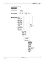
Page 62: ...Handbook OPTIFLEX 1300 C OPTIFLEX 1300 C 62 Finding the advanced setup menu...
Page 95: ...Handbook OPTIFLEX 1300 C 95 OPTIFLEX 1300 C Note...

