Handbook OPTIFLEX 1300 C
OPTIFLEX
1300
C
40
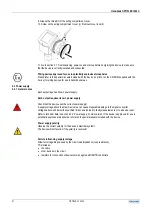
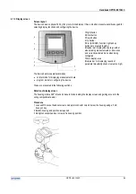
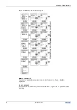
Special note: signal screen
This shows a line graph of voltage amplitude of return signals against distance. It is used for visually
identifying level and interface.
The top 5 to 10 peaks - representing the level, interface and interference signals - will be displayed and the
user can move to the next value to the right using the Right key. The voltage amplitude of the point (Y-axis)
and their distance from the device (X-axis) are displayed at the bottom of the screen.
A supervisor can modify level and interface thresholds and distance input manually to assist the device to
identify and track the products in difficult conditions.
Refer to section 4.1: hot keys and Section 4.4 Advanced setup: further notes for configuration procedures.
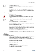
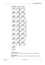
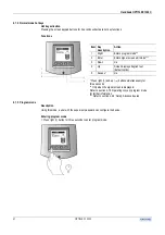
Icons in normal mode
Error icon
When a problem is detected in normal mode, an
error icon is displayed on the left of the display's
header bar. This is illustrated in the diagram below.
The error icon will remain displayed until a user with
supervisor access rights views the program mode
menu item B.2.12.0 Error records. See also section
4.2.4 advanced setup: further notes.
Summary of Contents for optiplex 1300 c
Page 1: ......
Page 49: ...Handbook OPTIFLEX 1300 C 49 OPTIFLEX 1300 C 1 Volume measurement of liquids...
Page 50: ...Handbook OPTIFLEX 1300 C OPTIFLEX 1300 C 50 2 Volume measurement of solids...
Page 51: ...Handbook OPTIFLEX 1300 C 51 OPTIFLEX 1300 C 3 Mass measurement of liquids or solids...
Page 62: ...Handbook OPTIFLEX 1300 C OPTIFLEX 1300 C 62 Finding the advanced setup menu...
Page 95: ...Handbook OPTIFLEX 1300 C 95 OPTIFLEX 1300 C Note...


