background image

Handbook OPTIFLEX 1300 C  


23 OPTIFLEX 

1300 


1.3.2


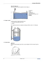
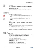
Tanks with concrete roofs 


Concrete roof thickness 

Install the device according to this rule; 


Ød => t 
 

where Ød is hole diameter and t is concrete thickness. 


If this rule cannot be obeyed, install the device in a recessed mounting as shown below on the right. 


1.3.3


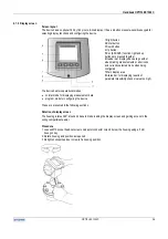
Stilling wells 


Applications  

Use a stilling well for these applications: 


where instructions for normal tank installation, such as the distance from the tank wall or tank internals, 

cannot be followed 


tanks with floating roofs for petro-chemical applications 


products with foam 


tanks with turbulent processes 


Summary of Contents for optiplex 1300 c

Page 1: ......

Page 2: ...with concrete roofs 23 1 3 3 Stilling wells 23 1 3 4 Bypass chambers 25 1 3 5 Spherical tanks 25 1 3 6 Horizontal cylindrical tanks 26 1 4 Other important information 27 1 4 1 Process conditions 27 1...

Page 3: ...nverter replacement 79 7 Technical data 80 7 1 Technical data 80 7 1 1 Technical data extract 80 7 1 2 Blocking distance 82 7 1 3 Hazardous areas 83 7 2 Dimensions and weights 83 8 Measuring principle...

Page 4: ...g the device screen wizard displays an error description which normally is sufficient to rectify the problem Only in severe cases will you need to consult the error records 0 1 2 Legal matters Authori...

Page 5: ...device in hazardous areas Please refer to the special manuals supplied on a CD ROM with the device Please read carefully In certain cases these instructions will replace standard installation and oper...

Page 6: ...Standards and approvals 0 4 1 Standards All versions of the device conform to European Union electromagnetic compatibility 89 336 CEE and low voltage equipment 73 23 CE Directives and Standards that...

Page 7: ...tion NPT G 16 Single rod probe 17 Single cable probe 18 Turnbuckle anchor for turbulent applications 19 Chuck anchor for turbulent applications 0 5 2 Non Ex namplate 1 Company name and address 2 Model...

Page 8: ...net for further information such as telephone fax and Email numbers of all KROHNE companies and representatives worldwide Items not supplied Nuts bolts gaskets and seals for fitting to existing nozzle...

Page 9: ...1300 C 9 OPTIFLEX 1300 C Fragile avoid hard blows impacts and jolts Storage Storage temperature Avoid bending rod and coaxial probes Avoid over bending cable probes Risk of measurement errors from ki...

Page 10: ...ormation on installation and applications refer to section 1 2 2 Location liquid applications and section 1 2 3 Location solid applications Refer also to section 1 3 Typical installations Hazardous ar...

Page 11: ...ting Nozzles Nozzle height Recommendation especially for single probes and powder applications Do not fit a nozzle longer than its diameter Nozzles extending into the tank Do not use nozzles that exte...

Page 12: ...rmation refer to section 4 2 4 Setup advanced setup Follow the procedures for modifying Gain and voltage amplitude of the level and or interface thresholds For further assistance contact the supplier...

Page 13: ...he cable must be far from other objects e g mixers to avoid entanglement Rigid length Lr of single and twin cable probes Installation relative to other tank components Objects near to the probe that i...

Page 14: ...tter may use a reference chamber or stilling well However the chamber must be smooth i e no visible weld lines with straight and vertical walls to maintain the pulse strength and measurement accuracy...

Page 15: ...nimum recommended free space around probe by type There is no beam angle for any probe type the limits of the EM field run parallel to the probe because the measurement pulse emitted by the device is...

Page 16: ...together single cable probes left and coaxial probes right 1 2 2 Liquid applications General notes Follow these instructions and those given in section 1 2 1 location all applications Turbulent produ...

Page 17: ...on By using the M8 hole underneath the counterweight other types of anchors for example spring rings and hooks can be fitted contact KROHNE for further details Tighten according to local rules and reg...

Page 18: ...Petroleum products These products may be stocked in vessels with moving roofs In this case install a stilling well according to local standards rules and regulations relative to the application and si...

Page 19: ...at which the tank is emptied Cable maximum design loads The 8mm or 0 3 single cable will fail at loads greater than 3 5 T or 7700 lbs There is also a risk of damage to pressure bearing components ins...

Page 20: ...al vessel or when the device is fitted with a coaxial probe it conforms to residential class immunity and emissions requirements All installations should respect the instructions given in section 1 2...

Page 21: ...hade 1 The sunshade is delivered separately attached to a metal tube A to prevent deformation of the mounting bracket 2 Unscrew two M6 socket head cap screws B with a 5 mm hexagonal key C 3 Remove the...

Page 22: ...g support pillar by bracing it with one hand Screw the two bolts tightly so that the sunshade does not slip down the pillar Procedure opening the sunshade 1 Insert a large screwdriver into the keyhole...

Page 23: ...is rule cannot be obeyed install the device in a recessed mounting as shown below on the right 1 3 3 Stilling wells Applications Use a stilling well for these applications where instructions for norma...

Page 24: ...ng well above the maximum product level an opening in the base is normally sufficient for one liquid applications if foam is not present drill other holes along the length of the stilling well this he...

Page 25: ...to tank base no roof deformation 6 Sediment 1 3 4 Bypass chambers Use bypass chambers for applications where there are too many protruding objects inside the tank agitators These installations have th...

Page 26: ...on relative to other tank components Refer to section 4 2 2 Setup device display conversion setup mode for configuring the meter to measure mass or volume in spherical tanks 1 3 6 Horizontal cylindric...

Page 27: ...rther information refer to relevant national standards For example European EN 1092 1 Flanges and their joints Circular flanges for pipes valves fittings and accessories PN designated Steel flanges US...

Page 28: ...to terminals is via a blue threaded cover on the side of the housing As the device is a 2 wire instrument the power supply and the output signal transmitted by the device use the same cable Reminder...

Page 29: ...rature Supply voltage The device requires a supply voltage that depends on which output terminal is used and the approval option ordered Refer to section 2 2 Power supply for this information Hazardou...

Page 30: ...loosen ground terminal screw e and insert wire Retighten screw See section 2 2 3 Power supply Ex versions for earth connection equipotential bonding system for Ex approved devices 6 Repeat steps 3 to...

Page 31: ...ts own power supply Check that the device uses the correct power supply A supply voltage above the maximum value can cause irreparable damage to the signal converter Voltages above and below the speci...

Page 32: ...C 32 2 2 2 Non Ex versions Non Ex or general purpose version One output standard Two outputs option 2 2 3 Ex versions Please refer to special manuals supplied with the device if it is approved for us...

Page 33: ...ts option Network options There are 3 output versions current output HART passive HART protocol current output Ex ia HART intrinsically safe passive HART protocol current output Ex d ia HART explosion...

Page 34: ...you want the device to communicate in multi drop mode then you have to change the output s HART address Use the following procedure Procedure using the display screen configuration wizard 1 Enter Pro...

Page 35: ...This level meter is set up in accordance with your order specifications You can use the device immediately If further adjustments are necessary we recommend configuration of the device using quick set...

Page 36: ...enu when being configured 7 Main display area 8 Status bar for displaying results of parameter plausibility checks value too high The device has two operational modes normal mode for displaying measur...

Page 37: ...e instrument s default mode 1 Header bar shows device tag number in normal mode 2 Measurement function 3 Measurement value and units Display styles Three display styles are available Value s Value s a...

Page 38: ...e with one output Interface measurement You can only choose screens with red borders when the device is configured for interface applications Mass measurement Select mass units and calibrate using con...

Page 39: ...ith two outputs Interface measurement You can only choose interface measurement screens when the device is configured for interface applications Mass measurement Select mass units and calibrate using...

Page 40: ...layed at the bottom of the screen A supervisor can modify level and interface thresholds and distance input manually to assist the device to identify and track the products in difficult conditions Ref...

Page 41: ...n n a 4 Up Screen displays English text default option 5 Escape n a Press right and up buttons simultaneously for three seconds Only when the signal screen is displayed Refer to section 4 1 5 Operatin...

Page 42: ...up right and enter 4A If the password is entered correctly the screen will show the main menu The name of the menu or sub menu entered is shown on the header bar 4B If the password is entered incorre...

Page 43: ...arameter Press right and up buttons simultaneously Editing values A value must be modified digit by digit The cursor starts at its default position on the digit the furthest to the left on the edit sc...

Page 44: ...message Returning to normal mode 1 Press escape several times to return to the Main Menu in program mode 2 Press escape again to return to normal mode If changes have been made to settings the user wi...

Page 45: ...PACTware Read the set up instructions in the text file ReadMe_Install_e supplied with PACTware and the DTM device type manager on the CD ROM delivered with the device The DTM has online help for under...

Page 46: ...Handbook OPTIFLEX 1300 C OPTIFLEX 1300 C 46 Finding setup mode The illustration below shows how to find quick setup menus from normal mode...

Page 47: ...ng the complete setup mode option you can configure all the items in the application installation conversion and output setup modes Application setup mode For defining the tank contents and setting th...

Page 48: ...ance Conversion setup mode For creating a conversion table for displaying volume mass or user defined unit measurements Due to the numerous possibilities available a procedural tree diagram is given f...

Page 49: ...Handbook OPTIFLEX 1300 C 49 OPTIFLEX 1300 C 1 Volume measurement of liquids...

Page 50: ...Handbook OPTIFLEX 1300 C OPTIFLEX 1300 C 50 2 Volume measurement of solids...

Page 51: ...Handbook OPTIFLEX 1300 C 51 OPTIFLEX 1300 C 3 Mass measurement of liquids or solids...

Page 52: ...e of inclination Calibrate volume as for other tanks No of LVM Entries This refers to the number of lines generated for typing in level and equivalent volume in the volume mass table Free units custom...

Page 53: ...PTIFLEX 1300 C 53 OPTIFLEX 1300 C Outputs setup mode For defining the measurement function and range digital network address and signal on alarm if interface is factory set or selected in Application...

Page 54: ...navigate to and configure advanced setup menu items using Quick link memory spaces given in the Quick Setup submenu Create a quick link Go to the required submenu via Program Mode Advanced Setup and s...

Page 55: ...As functions in advanced setup sub menu Setup mode for defining the process connection A 1 4 0 Conversion N a As functions in advanced setup sub menu Setup mode for creating a conversion table for dis...

Page 56: ...ing distance 0 m ft to probe length modif C 1 6 0 0 35 m or 13 The non measuring range at the top of the probe It depends on the probe type and the installation C 1 10 0 Reference offset tank height t...

Page 57: ...o be used in volume mass conversion table from the list If free unit is selected the unit given in item C 5 1 7 is used C 1 19 2 Conversion unit m L US gal GB gal ft bbl Tons kg US tons GB tons or fre...

Page 58: ...he behavior of the current output 1 in case an error occurs C 3 6 0 OP1 HART address 0 to 15 0 Any HART address greater than 0 will activate HART Multidrop mode current output fixed at 4mA C 4 0 0 Out...

Page 59: ...switch to the status set in C 5 1 2 Display mode C 5 1 4 Length unit m cm mm inch ft ft inch 1 18inch ft inch 1 32inch or free unit m Displayed length unit in normal mode C 5 1 5 Volume unit m L US ga...

Page 60: ...e mass 0 m Ullage volume mass 0 00 m3 0 00 Kg 20 mA setting for distance volume mass 0 m 0 Kg Layer 0 m 20 mA setting for layer 0 m Layer volume mass 0 00 m3 20 mA setting for layer volume mass 0 m Me...

Page 61: ...e re configured by a user with supervisor rights Using the advanced setup menu you can change the parameters for one or more functions without going through a quick setup procedure use individual menu...

Page 62: ...Handbook OPTIFLEX 1300 C OPTIFLEX 1300 C 62 Finding the advanced setup menu...

Page 63: ...able to display device information and change quick setup and advanced setup settings change the supervisor password Changing the supervisor password 1 From the Advanced Setup menu select the Device S...

Page 64: ...his is set at the factory to probe length Blocking distance function C 1 9 0 Refer to section 7 1 2 Technical data blocking distance for the minimum recommended value for a given probe type This preve...

Page 65: ...the signal and freeze the reading before it reaches the measuring range limit Level measurement As for distance measurement above level is influenced by tank height blocking distance The reference po...

Page 66: ...evice to measure level in terms of height above sea level Scaling the current output The current output setup mode is used to create current output scales for the first and second if ordered outputs t...

Page 67: ...1 8 Custom conv unit display function C 5 1 9 You can define your own length and conversion units with the last three functions When configuring the device to measure volume we recommend that you use...

Page 68: ...ket set screws 4 Reconfigure probe length in the device program mode as in the procedure above Single cable probe example 1 M6 socket set screws 2 retaining counterweight on the cable 2 4 mm or 0 15 c...

Page 69: ...the product it may be necessary increase the value of Gas r slightly to improve accuracy Also use this function if the probe is completely coated with a regular layer of residue or dust from the prod...

Page 70: ...roduct surface signal amplitude Level threshold function C 1 16 0 The graph below shows what the user would see if the return signals were displayed on an oscilloscope The level threshold function is...

Page 71: ...tank bottom following mode using the probe end as a reference In some cases the return signal may be so weak that manual adjustment on the probe end threshold is necessary to ignore interference sign...

Page 72: ...list using the up and down buttons to select the error log you want Five errors are listed per page scroll down the list to view other pages 1 Type of error 2 Brief description of error 3 Selection b...

Page 73: ...t is either not correct or frozen Fill tank to at least the bottom of the measuring range to continue measurement Interface measurement lost W The device can no longer find the interface Check the tan...

Page 74: ...ator support beam etc in the free space around the probes These produce parasite signals Either try to filter out the parasite signals using Level threshold function refer to section 4 2 4 Advanced se...

Page 75: ...end or install in a stilling well or bypass chamber Check the programmed probe length in Program Mode under Test Information Probe length If this does not correspond to the real value modify in Progr...

Page 76: ...n an emulsion may exist Wait for the device to find the interface again Signal status Reference pulse low amplitude W Reference amplitude falls below threshold 1 Fault common to solid applications whe...

Page 77: ...unctions 4 20 mA scale settings error handling and HART parameters B 2 2 0 15 min log Read only This displays a log of output values for the last 15 minutes A log is taken every 10 seconds and display...

Page 78: ...ys the application description of the measurement algorithm applied for the measurement function and application conditions Configured during application setup mode B 2 12 0 Error records Read only Se...

Page 79: ...E authorized service staff 6 2 Signal converter replacement Procedure Do not loosen flange bolts Disconnect the device from the power supply 1 Disconnect all wires refer also to Section 2 1 2 Wiring p...

Page 80: ...displayed in a variety of formats Error icon on display screen in normal mode Text warnings on display screen for errors in program mode Current output selectable 3 6 22 mA or Hold Errors warning flag...

Page 81: ...Double rod Stainless steel 316 L Hastelloy C 22 Coaxial Stainless steel 316 L Hastelloy C 22 Single cable Stainless steel 316 Hastelloy C 22 only cable 4 mm 0 15 Double cable Stainless steel 316 Proce...

Page 82: ...taken that is to say the counterweight turnbuckle and so on The measurement displayed on the gauge will freeze especially for cable probes L the probe length The length specified by the customer in th...

Page 83: ...the relevant special manual supplied on CD ROM or in printed form for devices approved for use in potentially explosive atmospheres 7 2 Dimensions and weights Level meter dimensions Dimensions in mm a...

Page 84: ...6 kg lb Housing 3 3 7 3 Flange connection DN 25 80 ANSI 1 3 4 7 8 8 15 4 Flange connection DN 100 150 ANSI 4 6 7 12 15 4 26 5 Thread connection 3 6 6 Weight Probes kg m lb ft Single cable 4mm or 0 15...

Page 85: ...instrument and converted into a signal amplitude in volts The instrument measures the time between the emission and the reception of the signal half of this time corresponds to the distance from the...

Page 86: ...nce to the interface can be calculated by the device if the distance to the top product surface and the top product s dielectric constant are known The layer defined as the depth of the top product to...

Page 87: ...tank is full or partially filled and the time it takes for the pulse to be reflected back from the probe end when the tank is empty is proportional to product level The diagram below shows how TDR wor...

Page 88: ...k OPTIFLEX 1300 C OPTIFLEX 1300 C 88 The waveforms below the diagrams shows a snapshot of what the user would see on an oscilloscope where V1 speed of light in a gas and V2 speed of light through the...

Page 89: ...provals for the CE marking are standard When ordered with the appropriate options the device can be approved for use in hazardous areas All approvals and certificates are available on the KROHNE inter...

Page 90: ...ee space and can potentially influence the electromagnetic field around the probe This can cause a measurement error See also section 1 2 1 Location all applications Distance Distance from the face of...

Page 91: ...gradual mix from 0 to 100 water 6 water F Free space A zone given as a minimum diameter around a probe that should have no objects in it for a gauge to correctly measure level Size depends on probe t...

Page 92: ...back to the device and processed O Operator User who has rights to use all menu items in normal mode Device configuration in program mode is not allowed P Probe Either a metallic cable or rod used to...

Page 93: ...by the OPTIFLEX 1300 to measure level and interface See also section 9 1 General principle Threshold A number of limits set either manually or automatically by the signal converter to identify the lev...

Page 94: ...t the device is safe to handle If the device has been operated with toxic caustic flammable or water endangering products you are kindly requested to check and ensure if necessary by rinsing or neutra...

Page 95: ...Handbook OPTIFLEX 1300 C 95 OPTIFLEX 1300 C Note...

Reviews: