Konica Minolta bizhub C35 Service Manual Download Page 27

DRAFT

C-2

Notation of the service manual

A. Product name

In this manual, each of the products is described as follows:

B. Brand name

The company names and product names mentioned in this manual are the brand name or

the registered trademark of each company.

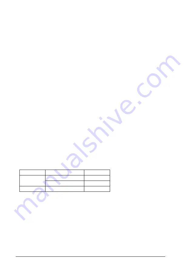
C. Feeding direction

• When the long side of the paper is parallel with the feeding direction, it is called short

edge feeding. The feeding direction which is perpendicular to the short edge feeding is
called the long edge feeding.

• Short edge feeding will be identified with [S (abbreviation for Short edge feeding)] on the

paper size. No specific notation is added for the long edge feeding. 
When the size has only the short edge feeding with no long edge feeding, [S] will not be
added to the paper size.

<Sample notation>

(1) magicolor 1600W/magicolor 1650EN

Main body

(2) Microsoft Windows NT 4.0:

Windows NT 4.0 or Windows NT

Microsoft Windows 2000:

Windows 2000

Microsoft Windows XP:

Windows XP

Microsoft Windows 

V

ista:

Windows 

V

ista

When the description is made in combination of the OS’s mentioned above:

Windows NT 4.0/2000

Windows NT/2000/XP/

V

ista

Paper size

Feeding direction

Notation

A4

Long edge feeding

A4

Short edge feeding

A4S

A3

Short edge feeding

A3

Summary of Contents for bizhub C35

Page 1: ...DRAFT SERVICE MANUAL 2010 02 2010 02 Ver 1 0 Ver 1 0 FIELD SERVICE ...

Page 2: ...ARNINGS S 2 SAFETY INFORMATION S 18 IMPORTANT NOTICE S 18 INDICATION OF WARNING ON THE MACHINE S 19 MEASURES TO TAKE IN CASE OF AN ACCIDENT S 22 Composition of the service manual C 1 Notation of the service manual C 2 bizhub C35 Main body OUTLINE 1 MAINTENANCE 7 ADJUSTMENT SETTING 97 TROUBLESHOOTING 189 APPENDIX 263 Lower Feeder Unit OUTLINE 1 MAINTENANCE 3 ...

Page 3: ...DRAFT ii Blank Page ...

Page 4: ... in the course of technical training and even after that for performing maintenance and control of the product properly Keep this Service Manual also for future service In this Service Manual each of three expressions DANGER WARNING and CAUTION is defined as follows together with a symbol mark to be used in a limited meaning When servicing the product the relevant works disassembling reassembling ...

Page 5: ...n performance and safety Such modifications are therefore strictly prohibited The points listed below are not exhaustive but they illustrate the reason ing behind this policy SAFETY WARNINGS Prohibited Actions DANGER Using any cables or power cord not specified by KMBT Using any fuse or thermostat not specified by KMBT Safety will not be assured leading to a risk of fire and injury Disabling fuse ...

Page 6: ... having enough cur rent capacity and the cord set meets regulatory requirements for the area Use of inadequate cord set leads to fire or electric shock Attach power plug which meets the following criteria having configuration intended for the connection to wall outlet appropriate for the product s rated voltage and current and the plug has pin terminal s for grounding and meets regulatory requirem...

Page 7: ...ug directly into wall outlet having same configuration as the plug Use of an adapter leads to the product connecting to inadequate power supply voltage current capacity grounding and may result in fire or electric shock If proper wall outlet is not available advice the customer to contact qualified electrician for the installation Plug the power cord into the dedicated wall outlet with a capacity ...

Page 8: ...the cord with the fixture properly If the power cord inlet type is not connected to the prod uct securely a contact problem may lead to increased resistance overheating and risk of fire Check whether the power cord is not stepped on or pinched by a table and so on Overheating may occur there leading to a risk of fire Check whether the power cord is damaged Check whether the sheath is damaged If th...

Page 9: ...ng the power cord grasp the plug not the cable The cable may be broken leading to a risk of fire and electric shock Power Plug and Cord WARNING Wiring WARNING Never use multi plug adapters to plug multiple power cords in the same outlet If used the risk of fire exists When an extension cord is required use a specified one Current that can flow in the extension cord is limited so using a too long e...

Page 10: ... used over an extended period of time holidays etc switch it off and unplug the power cord Dust collected around the power plug and outlet may cause fire Ventilation CAUTION The product generates ozone gas during operation but it will not be harmful to the human body If a bad smell of ozone is present in the following cases ventilate the room a When the product is used in a poorly ventilated room ...

Page 11: ...wer plugs from the product and options When the power plug is inserted in the wall outlet some units are still powered even if the POWER switch is turned OFF Arisk of electric shock exists The area around the fixing unit is hot You may get burnt Work Performed with the Product Powered On WARNING Take every care when making adjustments or performing an operation check with the product powered If yo...

Page 12: ...ent can leak leading to a risk of electric shock or fire Carefully remove all toner remnants and dust from electri cal parts and electrode units such as a charging corona unit Current can leak leading to a risk of product trouble or fire Check high voltage cables and sheaths for any damage Current can leak leading to a risk of electric shock or fire Check electrode units such as a charging corona ...

Page 13: ...k the installa tion state A risk of fire exists Check the interlock switch and actuator for loosening and check whether the interlock functions properly If the interlock does not function you may receive an electric shock or be injured when you insert your hand in the product e g for clearing paper jam Make sure the wiring cannot come into contact with sharp edges burrs or other pointed parts Curr...

Page 14: ...e You may be burned due to dust explosion Handling of Service Materials CAUTION Unplug the power cord from the wall outlet Isopropyl alcohol and acetone are highly flammable and must be handled with care A risk of fire exists Do not replace the cover or turn the product ON before any solvent remnants on the cleaned parts have fully evaporated A risk of fire exists Use only a small amount of cleane...

Page 15: ...lent recom mandé par le constructeur Mettre au rebut les batteries usagées conformément aux instructions du fabricant Denmark ADVARSEL Lithiumbatteri Eksplosionsfare ved fejlagtig håndtering Udskiftning må kun ske med batteri af samme fabrikat og type Levér det brugte batteri tilbage til leverandøren Finland Sweden VAROlTUS Paristo voi räjähtää jos se on virheellisesti asennettu Vaihda paristo ain...

Page 16: ...ure of the Print Head Unit This product employs a Class 3B laser diode that emits an invisible laser beam The laser diode and the scanning polygon mirror are incorporated in the print head unit The print head unit is NOT A FIELD SERVICEABLE ITEM Therefore the print head unit should not be opened under any circumstances semiconductor laser Maximum power of the laser diode 15 mW Maximum average radi...

Page 17: ...s and must be attached to laser products marketed in the United States All Areas Denmark CAUTION Use of controls adjustments or performance of procedures other than those specified in this manual may result in hazardous radiation exposure semiconductor laser Maximum power of the laser diode 15 mW Wavelength 770 800 nm CAUTION Use of controls adjustments or performance of procedures other than thos...

Page 18: ...kan användaren utsättas för osynlig laserstrålning som överskrider gränsen för laserklass 1 halvledarlaser Den maximala effekten för laserdioden 15 mW våglängden 770 800 nm VARO Avattaessa ja suojalukitus ohitettaessa olet alttiina näkymättomälle laser säteilylle Älä katso säteeseen VARNING Osynlig laserstråining när denna del är öppnad och spärren är urkopplad Betrakta ej stråien ADVERSEL Dersom ...

Page 19: ...DRAFT SAFETY AND IMPORTANT WARNING ITEMS S 16 4 2 Laser Safety Label A laser safety label is attached to the inside of the machine as shown below A121P0E505DA ...

Page 20: ... conforming to the above specifications When a disassembly job needs to be performed in the laser beam path such as when working around the printerhead and PC Drum be sure first to turn the printer OFF If the job requires that the printer be left ON take off your watch and ring and wear laser protective goggles A highly reflective tool can be dangerous if it is brought into the laser beam path Use...

Page 21: ...the United States This copier is certified as a Class 1 laser product under the U S Department of Health and Human Services DHHS Radiation Performance Standard according to the Radiation Control for Health and Safety Act of 1968 Since radiation emit ted inside this copier is completely confined within protective housings and external covers the laser beam cannot escape during any phase of normal u...

Page 22: ...ne When accessing these areas for maintenance repair or adjustment special care should be taken to avoid burns and electric shock INDICATION OF WARNING ON THE MACHINE A121P0C503DA CAUTION The area around the Fuser Unit is extremely hot Touching any part other than those indicated may result in burns ...

Page 23: ...en the power is turned ON to avoid getting an electric shock High voltage This area generates high voltage Be careful not to touch here when the power is turned ON to avoid getting an electric shock Electric hazard To avoid electrical shock after turning OFF the power switch do not touch the DC power supply for 9 minutes ...

Page 24: ...lled from the fire is dangerous WARNING Do not burn used Waste Toner Bottle Toner expelled from the fire is dangerous You may be burned or injured if you touch any area that you are advised by any caution label to keep yourself away from Do not remove caution labels And also when the caution label is peeled off or soiled and cannot be seen clearly replace it with a new caution label ...

Page 25: ...rt of a serious accident has been received from a customer an on site evalua tion must be carried out quickly and KMBT must be notified 3 To determine the cause of the accident conditions and materials must be recorded through direct on site checks in accordance with instructions issued by KMBT 4 For reports and measures concerning serious accidents follow the regulations speci fied by every distr...

Page 26: ... information The basic configuration of each section is as follows However some options may not be applied to the following configuration Theory of Operation section Field service section OUTLINE Explanation of system configuration product specifications unit configuration and paper path COMPOSITION OPERATION Explanation of configuration of each unit operating system and control system OUTLINE Exp...

Page 27: ...g will be identified with S abbreviation for Short edge feeding on the paper size No specific notation is added for the long edge feeding When the size has only the short edge feeding with no long edge feeding S will not be added to the paper size Sample notation 1 magicolor 1600W magicolor 1650EN Main body 2 Microsoft Windows NT 4 0 Windows NT 4 0 or Windows NT Microsoft Windows 2000 Windows 2000...

Page 28: ...DRAFT SERVICE MANUAL 2010 02 Ver 1 0 FIELD SERVICE Main body ...

Page 29: ...ide represents the number of times the revision has been made To indicate clearly a page that contains the revision is shown near the page number of the corresponding page The number inside represents the number of times the revision has been made NOTE Revision marks shown in a page are restricted only to the latest ones with the old ones deleted When a page revised in Ver 2 0 has been changed in ...

Page 30: ...Replacing the imaging unit C M Y K 11 4 2 Transfer section 14 4 2 1 Replacing the waste toner bottle 14 4 2 2 Replacing the transfer roller unit 15 4 2 3 Replacing the transfer belt unit 16 4 3 Fusing section 20 4 3 1 Replacing the fuser unit 20 4 4 Feed section 22 4 4 1 Replacing the tray1 feed roller 22 4 4 2 Replacing the tray2 feed roller 24 5 SERVICE TOOL 25 5 1 Service material list 25 5 2 C...

Page 31: ... 13 FAX board FAXB 57 7 4 14 MFP board MFPB 58 7 4 15 Printer control board PRCB 62 7 4 16 DC power supply DCPU 64 7 4 17 High voltage unit HV1 66 7 4 18 PH Unit 67 7 4 19 Backup battery 69 7 4 20 Developing motor M1 71 7 4 21 Main motor M2 71 7 4 22 Color PC drum motor M4 71 7 4 23 DC power supply fan motor FM10 72 7 4 24 Cooling fan motor FM11 72 7 4 25 MFP board cooling fan motor FM12 73 7 4 26...

Page 32: ... 2 Starting Exiting 103 9 2 1 Starting procedure 103 9 2 2 Exiting procedure 103 9 3 Statistics Page 104 9 3 1 Sample of STATISTICS PAGE 104 9 4 Restore Defaults 109 10 SERVICE MODE 118 10 1 List of service mode 118 10 2 Starting Exiting 121 10 2 1 Starting procedure 121 10 3 Serial Number 122 10 4 Firmware Version 122 10 5 Printer Adjustment 123 10 5 1 Leading Edge Adjustment 123 10 5 2 Side Edge...

Page 33: ...4 Dis 133 10 7 8 RX V34 OFF 133 10 7 9 V17 Mod Permit 133 10 7 10 Retry Start Pg 134 10 7 11 DT Detect 134 10 7 12 BT Detect 134 10 7 13 Cable Equalize 134 10 7 14 Echo Measure 134 10 7 15 CFR to Phase C 135 10 7 16 TX Level 135 10 7 17 Connect Timeout 135 10 7 18 CED Level 135 10 7 19 eRTN 136 10 7 20 V34 Symbol Rate 136 10 7 21 Data Format 136 10 7 22 V34 Tran Pt 136 10 7 23 Fax Target 136 10 7 ...

Page 34: ...F 152 10 8 14 Tilt B 152 10 9 Print Menu 153 10 9 1 Mgmt List 153 10 9 2 Event Log 155 10 9 3 Adjust Information 155 10 9 4 Element Page 156 10 9 5 Halftone 64 157 10 9 6 Halftone 128 157 10 9 7 Halftone 256 157 10 9 8 Gradation 158 10 9 9 Scanner Adjustment 158 10 9 10 Scan Event Log 158 10 10 Supplies 158 10 10 1 Consumable Replace Transfer Belt Unit 158 10 10 2 Consumable Replace Transfer Rolle...

Page 35: ...nt Mode 171 10 14 3 Large Paper size Mode 171 10 15 Clear Admin Password 171 10 16 CE Password 172 10 17 Soft Switch 172 10 18 Engine DipSW 172 10 19 Function 173 10 19 1 Print Test Print A4 Test Print Letter 173 10 19 2 Comp Check 173 10 19 3 Sensor Check Scanner Sensor Check 175 10 20 Toner Out Mode 176 10 21 IU Yield Settings 176 10 22 Enable Warning 177 10 22 1 Toner Low 177 10 22 2 Imaging Un...

Page 36: ...ROMATION 201 13 1 Display procedure 201 13 2 List 201 13 3 Solution 201 13 3 1 Temperature humidity sensor failure 201 13 3 2 IDC sensor failure 202 13 3 3 Color regist test pattern failure 202 13 3 4 Color regist adjust failure 202 14 MALFUNCTION CODE 203 14 1 Trouble code Service Call 203 14 2 List 203 14 3 Trouble resetting procedure 206 14 4 Solution 207 14 4 1 0010 Color PC drum motor malfunc...

Page 37: ... 215 14 4 27 6790 Offset adjustment error 215 14 4 28 6792 White reference plate search error 215 14 4 29 6793 Scanner communication error 215 14 4 30 9401 Lamp illumination check error 215 14 4 31 6791 Register setting error 216 14 4 32 B116 Communication error with the fax board 217 14 4 33 C023 Flash ROM error 217 14 4 34 C025 Controller ROM error Configuration information error 217 14 4 35 C02...

Page 38: ...irection 235 16 2 13 Printer monocolor white lines white bands colored lines and colored bands in main scan direction 236 16 2 14 Printer monocolor uneven density in sub scan direction 237 16 2 15 Printer monocolor uneven density in main scan direction 238 16 2 16 Printer monocolor low image density 239 16 2 17 Printer monocolor gradation reproduction failure 240 16 2 18 Printer monocolor foggy ba...

Page 39: ...er 4 color back marking 258 16 2 36 Printer 4 color uneven image 259 17 IC protector 260 17 1 Outline 260 17 2 IC protector list 260 17 2 1 Main body 260 17 2 2 Lower feeder unit PF P08 261 APPENDIX 18 PARTS LAYOUT DRAWING 263 18 1 Main body 263 18 2 ADF 267 18 3 Lower feeder unit option 268 19 CONNECTOR LAYOUT DRAWING 269 19 1 Printer control board PRCB 269 19 2 MFP board MFPB 270 19 3 FAX board ...

Page 40: ...on Ver 1 0 Feb 2010 1 SYSTEM CONFIGURATION 1 Lower feeder unit OUTLINE OUTLINE 1 SYSTEM CONFIGURATION To be locally procured for North America Europe 1 bizhub C35 2 PF P08 Lower feeder unit 3 DK P01 Desk A0VDT2C544AA 1 2 2 3 ...

Page 41: ...0 x 600 dpi x 3bit Paper feeding system Tray1 100 sheets Tray2 250 sheets Tray3 500 sheets Option Developing system Single element developing system Charging system Charge roller system Image transfer system Intermediate transfer belt system Paper separating system Curvature separation charge neutralizing system Fusing system Belt fusing Paper exit system Face down Output tray capacity 250 sheets ...

Page 42: ...h 92 to 216 mm 3 6 to 8 5 inch Length 148 to 356 mm 5 8 to 14 0 inch 148 to 356 mm 5 8 to 14 0 inch Machine durability 400 000 prints or 5 years whichever comes first Power requirements Voltage AC 100V 120 V 220 to 240 V Frequency 50 to 60 Hz Max power consumption 1 200 W or less 100 V 120 V 1 100 W or less 110 V 1 300 W or less 127 V 220 240 V Dimensions 530 W x 508 D x 550 H mm 20 87 W x 20 00 D...

Page 43: ... 5 Linux SUSE Linux Enterprise Desktop 10 CUPS Ver 1 1 23 Red Hat Enterprise Linux 5 Desktop CUPS Ver 1 2 4 Printer driver PCL6 Windows 2000 XP Server 2003 Vista Server 2008 printer driver Windows XP Server 2003 Vista Server 2008 x64 Edition printer driver Windows 2000 XP Server 2003 Vista Server 2008 printer driver for monochrome printing Windows XP Server 2003 Vista Server 2008 x64 Edition print...

Page 44: ... in the super fine mode Functions Abbreviated dial Max 2000 stations to be registered Program dial Max 400 numbers to be registered Key pad dial 38 digits maximum during off hook dial mode 60 digits maximum during on hook dial mode Group dial Max 100 numbers to be registered Up to 500 abbreviated dial numbers can be registered for each group Manual redial Possible to select from five latest histor...

Page 45: ...ne Depends on country spec Busy tone Depends on country spec Dialing system To be selected from among PB 10 pps and 20 pps Line monitoring sound ON A B Monitoring sound is sounded for communication phase between A and B ON All Monitoring sound is sounded for communication phase between A and E OFF Monitoring sound is not sounded Off Hook alarm Notifies the user if the external telephone is off hoo...

Page 46: ...arts life for details Class Part to be replaced Number of prints Description Ref page Processing section Imaging unit C M Y K 30 000 Continuous printing 20 000 2P J 1 P 11 Standard in box toner car tridge C M Y K 6 000 Continuous printing P 8 High capacity toner cartridge C M Y K 6 000 Continuous printing Image transfer section Waste toner bottle WB P03 36 000 monochrome Continuous printing P 14 9...

Page 47: ...C M Y K A Periodically replaced parts cycle Standard in box toner cartridge C M Y K Every 6 000 counts High capacity toner cartridge C M Y K Every 6 000 counts B Removal procedure 1 Open the front cover 1 2 Slide the lock lever 1 to the left 3 Grab the handle of the toner car tridge 1 to be replaced and then pull out the toner cartridge 1 A121F2C500DA 1 Y M C K A121F2C501DA 1 A121F2C502DA 1 ...

Page 48: ...NTENANCE C Reinstallation procedure 1 Take the toner cartridge 2 out of its plastic bag 1 2 Gently shake the toner cartridge 1 three times to agitate the toner 3 Peel off the protective film tape 1 from the right side of the toner car tridge A0VDF2C521DA 1 2 3 A0VDF2C522DA 1 A0VDF2C523DA 1 ...

Page 49: ...Feb 2010 10 bizhub C35 MAINTENANCE 4 Insert the toner cartridge 1 into the machine 5 Slide the lock lever 1 to the right to lock the toner cartridge 6 Remove the protective film 1 7 Close the front cover 1 A121F2C503DA 1 A121F2C504DA 1 A121F2C505DA 1 A121F2C506DA 1 ...

Page 50: ...iodically replaced parts cycle Imaging unit C M Y K Every 30 000 counts B Removal procedure 1 Remove the toner cartridge See P 8 2 Remove the waste toner bottle See P 14 3 Press down the Push marked place 1 4 Pull the imaging unit 2 out C Reinstallation procedure 1 Take the imaging unit 1 out of the plastic bag A121F2C507DA 2 1 A0VDF2C529DA 1 2 ...

Page 51: ...it with both hands and then shake it twice as shown in the illustration 3 Remove the protective cover 1 from the imaging unit 4 Remove all packing tape 2 from the imaging unit 5 Remove the paper 1 from the imag ing unit 6 Remove the protective cover 2 from the imaging unit A0VDF2C530DA A0VDF2C531DA 2 1 A0VDF2C532DA 1 2 ...

Page 52: ... 1 0 Feb 2010 4 PERIODICAL MAINTENANCE PROCEDURE 13 bizhub C35 MAINTENANCE 7 Slide the imaging unit 1 in 8 Install the waste toner bottle See P 14 9 Install the toner cartridge See P 8 10 Close the front cover A121F2C508DA 1 ...

Page 53: ...lly replaced parts cycle Waste toner bottle Every 36 000 counts monochrome 9 000 counts full color B Removal procedure 1 Open the front cover 1 2 Raise the left and right handles 1 to unlock the waste toner bottle 3 Grab the left and right handles 1 remove the waste toner bottle 2 4 To reinstall reverse the order of removal A121F2C500DA 1 A121F2C509DA 1 A121F2C510DA 1 ...

Page 54: ...o unlock the transfer roller 3 Rotate the transfer roller unit 2 in the direction of the arrow 4 Remove the transfer roller unit 1 5 To reinstall reverse the order of removal 6 From the Menu select Service Mode Supplies Consumables Replace Transfer Roller Unit and execute this function to reset the transfer roller counter value 7 From the Menu select Admin Setting Printer Setting Quality Settings ...

Page 55: ... machine does not start to print jobs before the counter value of the transfer belt unit is reset Make sure that the machine does not have print jobs and fax reception data wait ing to print Be sure to disconnect the USB cable the network cable and the fax cable from the machine 1 Turn OFF the power switch 2 Remove the toner cartridge C M Y K See P 8 3 Remove the waste toner bottle See P 14 4 Remo...

Page 56: ...with the transfer belt unit in the direction of the arrow NOTE If the protective sheet is not sup plied use two sheets of A4 or Letter paper as shown in the illustration 8 Hold the both handles 1 and lower the guide 2 9 Hold the handles and then carefully pull out the transfer belt unit 1 A121F2C555DA 1 A121F2C556DA 1 A121F2C517DA 1 2 A121F2C518DA 1 ...

Page 57: ...he protective sheet 1 out 11 Remove the protective cover 1 from the new transfer belt unit NOTE Be careful not to touch the surface of the belt 12 Insert the transfer belt unit 2 along the rail 1 13 Hold the both handles 1 and raise the guide 2 A121F2C557DA 1 A0VDF2C536DA 1 A121F2C519DA 2 1 A121F2C559DA 1 2 ...

Page 58: ...cable and the fax cable are not con nected to the machine 16 From the Menu select Service Mode Supplies Consumables Replace Transfer Belt Unit and execute this function to reset the transfer belt unit counter value 17 From the Menu select Admin Setting Printer Setting Quality Settings Gra dation Adjust AIDC Process and execute this function 18 Connect the USB cable the network cable and the fax ca...

Page 59: ...ower switch unplug the power cord from the power outlet and let the machine to stand idle for about 20 min 2 Open the right door 1 3 Open the fuser unit cover 1 CAUTION The temperature gets high in the vicinity of the fuser unit You may get burned when you come into contact with the area Before replacement operations make sure that more than 20 minutes have elapsed since the main and sub power swi...

Page 60: ...1 bizhub C35 MAINTENANCE 4 Pull down two levers 1 5 Remove the fuser unit 1 6 Install the new fuser unit 7 From the Menu select Service Mode Supplies Consumables Replace Fusing Unit and execute this function to reset the fuser unit counter value A121F2C523DA 1 A121F2C524DA 1 ...

Page 61: ...acing the tray1 feed roller A Periodically replaced parts cycle Tray1 feed roller Every 300 000 counts B Procedure 1 Remove the tray1 See P 54 2 Open the right door 3 Detach the spring 1 from the hook 2 in order to unlock the plate 4 Remove six screws 1 and remove the tray1 feed roller assy 2 A121F2C001DA 2 1 A0VDF2C001DA 1 2 ...

Page 62: ...ing the tray 1 feed roller assy the stopper 1 must be located under the shaft 2 as shown in the illustration 6 Remove the E ring 1 and mecha nism clutch 2 and remove the tray1 feed roller 3 7 To reinstall reverse the order of removal NOTE When reinstalling the feed roller 1 make sure that it is mounted in the direction shown in the illustration on the left A0VDF2C003DA 1 2 3 A0VDF2C004DA 1 2 A0VDF...

Page 63: ...00 counts B Procedure 1 Remove the tray2 See P 55 2 Lock the media lift metal plate 1 3 Remove two E rings 2 and the bearing 3 4 Remove the C ring 1 and remove the tray2 feed roller 2 5 To reinstall reverse the order of removal NOTE When reinstalling the feed roller 1 make sure that it is mounted in the direction shown in the illustration on the left A121F2C002DA 2 3 1 A121F2C003DA 1 2 1 A0VDF2C54...

Page 64: ...ENANCE 5 SERVICE TOOL 5 1 Service material list 5 2 CE tool list Tool name Shape Material No Remarks Cleaning pad 000V 18 1 10pcs 1pack Isopropyl alcohol 000V 19 0 A02EF2C526DA A00KF2C506DA Tool name Shape Quantity Parts No Laser lens cleaning tool 1 A0VD 1089 A0VDF2C553DA ...

Page 65: ...mware upgrading A System requirements PC equipped with a USB port USB memory device B Saving the firmware data into the USB memory device 1 Save the firmware data in appropriate space in the PC 2 Connect the USB memory device to the PC 3 Create a firmware folder immediately under the drive of the USB memory device 4 Copy the firmware data exe in the firmware folder created in step 3 NOTE Be sure t...

Page 66: ...rn the power switch ON 2 Connect the USB memory device to the printer 3 Display Service Mode 4 Press Firmware Update 5 A list of firmware data in the USB memory device is displayed NOTE Before upgrading firmware use Details to check that the firmware data is correct 6 Press Close A121F2C534DA A121F2C535DA A121F2C536DA ...

Page 67: ...requirements A121F2C537DA Computer Windows PC with a Pentium 2 400 MHz or faster processor A Pentium 3 500 MHz or faster processor is recommended Macintosh Apple Macintosh computer with a PowerPC G3 or later proces sor A PowerPC G4 or later is recommended Apple Macintosh computer with an Intel processor OS Windows Microsoft Windows XP Home Edition Professional Windows 2000 Windows Vista Home Basic...

Page 68: ...fore starting the firmware updater turn on the printer and make sure that it is correctly connected 1 Download the firmware updater 2 Double click xxxxxxxxxxxx exe 3 The printer name and firmware version are displayed Click the Next 4 The license agreement is displayed Select I agree and then click the Next A121F2E537DA XXXXXXX XXXXXXX A011F2E556DA ...

Page 69: ...a network connection Select Network port See P 31 For a local connection Select Local port See P 34 When specifying the IP address of the printer Select Printer IP address See P 35 NOTE If you select Network port or Local port make sure that the printer driver has been installed If you select Printer IP address the firmware can be updated even if a printer driver is not already installed A121F2E53...

Page 70: ... is selected a list of printer drivers for the network port appears 2 Select the printer driver and then click the Next 3 A message appears requesting confirmation to update the firmware Click the Start to begin transferring the firmware NOTE Do not turn off the printer while its firmware is being updated A011F2E558DA A011F2E559DA ...

Page 71: ...ITING Field Service Ver 1 0 Feb 2010 32 bizhub C35 MAINTENANCE 4 The result of the firmware transfer is displayed Click the Exit 5 If the firmware was successfully updated the printer will automatically restart A011F2E560DA ...

Page 72: ...ta fails NOTE If spooling fails data may remain in the printer spooler Delete this data and then try again 1 If spooling of the data fails the following message appears 2 Click OK 3 Check that the printer is ready and that it is correctly connected and then click the Update again A011F2E561DA A011F2E562DA ...

Page 73: ...is selected a list of printer drivers for the local port appears 2 Select the printer driver and then click the Next 3 A message appears requesting confirmation to update the firmware Click the Start to begin transferring the firmware NOTE Do not turn off the printer while its firmware is being updated A011F2E563DA A011F2E564DA ...

Page 74: ... firmware was successfully updated the printer will automatically restart If spooling of the data fails For details see For a network connection See P 33 4 When specifying the IP address of the printer 1 When Printer IP address is selected the Printer IP address box becomes available 2 Type in the IP address and then click the Next A011F2E565DA A011F2E566DA ...

Page 75: ...mation to update the firmware Click the Start to begin transferring the firmware NOTE Do not turn off the printer while its firmware is being updated 4 The result of the firmware transfer is displayed Click the Exit 5 If the firmware was successfully updated the printer will automatically restart A011F2E567DA A011F2E565DA ...

Page 76: ... bizhub C35 MAINTENANCE If transferring of the data fails 1 If transferring of the data fails the following message appears 2 Click OK 3 Check that the printer is ready and that it is correctly connected and then click the Update again A011F2E569DA A011F2E570DA ...

Page 77: ...e NOTE Before starting the firmware updater turn on the printer and make sure that it is correctly connected 1 Download the firmware updater 2 Double click xxxxxxxxxxxx 3 The printer name and firmware version are displayed Click the Next 4 The license agreement is displayed Select I agree and then click the Next A121F2E539DA KONICA MINOLTA XXXXXXXX XXXXX A011F2E572DA ...

Page 78: ... the IP address of the printer appears 6 Type in the IP address and then click the Next 7 A message appears requesting confirmation to update the firmware Click the Start to begin transferring the firmware NOTE Do not turn off the printer while its firmware is being updated A011F2E573DA A011F2E574DA A011F2E575DA ...

Page 79: ... the Exit 9 If the firmware was successfully updated the printer will automatically restart If transferring of the data fails 1 If transferring of the data fails the following message appears 2 Click OK 3 Check that the printer is ready and that it is correctly connected and then click the Update again A011F2E576DA A011F2E577DA A011F2E578DA ...

Page 80: ...2010 6 FIRMWARE REWRITING 41 bizhub C35 MAINTENANCE 6 3 2 Checking the version after the firmware update 1 Display Service Mode 2 Display Firmware Version 3 Select the firmware to be updated and check the current version A121F2C533DA ...

Page 81: ...being removed by mistake Do not remove or loosen any of the red painted screws in the field It should also be noted that when two or more screws are used for a single part only one repre sentative screw may be marked with the red paint C Variable resistors on board NOTE Do not turn the variable resistors on boards for which no adjusting instructions are given in Adjustment Setting D Removal of PWB...

Page 82: ...ADF separation pad P 51 Scanner unit P 52 Tray1 P 54 Tray2 P 55 Hard disk HDD P 55 PH unit P 67 Other parts Backup battery P 69 Developing motor M1 P 71 Main motor M2 P 71 Color PC drum motor M4 P 71 DC power supply fan motor FM10 P 72 Cooling fan motor FM11 P 72 MFP board cooling fan motor FM12 P 73 Tray2 media feed clutch CL1 P 74 Tray1 media feed clutch CL2 Registration clutch CL3 P 75 Toner su...

Page 83: ...e P 55 2 Remove the waste toner bottle See P 14 3 Remove three C rings 1 and remove the front door 2 7 4 2 Rear cover 1 Remove two screws 1 and remove the rear cover 2 as shown in the illustration Section Part name Ref Page Tray1 Tray1 feed roller P 92 Tray2 Tray2 feed roller P 92 ADF ADF feed roller P 93 Processing section Laser irradiation section P 93 A121F2C004DA 1 2 A121F2C005DA 1 2 ...

Page 84: ...4 2 Slide out the tray 2 3 Open the front cover 4 Remove the cover 1 5 Remove three screws 1 and remove the left cover 2 7 4 4 Rear right cover 1 Remove the ADF See P 47 2 Remove the scanner unit See P 52 3 Open the right door 4 Remove three screws 1 and remove the rear right cover 2 A121F2C543DA 1 A121F2C006DA 1 1 2 A121F2C007DA 1 1 2 ...

Page 85: ... 2010 46 bizhub C35 MAINTENANCE 7 4 5 Operation panel 1 Remove the operation panel lower cover 1 2 Remove the screw 1 3 Disconnect the connector 2 and remove the operation panel 3 4 To reinstall reverse the order of removal A121F2C008DA 1 A121F2C009DA 2 3 1 ...

Page 86: ... ADF feed cover 1 2 Unhook two tabs 1 and remove the ADF document feed tray 2 3 Remove three screws 1 and remove the ADF rear cover 2 CAUTION Turn OFF the main power and then wait 15 seconds or more before dis connecting the connector from the DF control board A121F2C528DA 1 A121F2C010DA 1 2 A121F2C011DA 1 2 ...

Page 87: ...INTENANCE 4 Remove the screw 1 and remove the clamp 2 5 Remove the ferrite core 3 6 Disconnect the connector J1 4 7 Pull the cable 1 out 8 While pushing two tabs 1 remove the ADF 2 9 To reinstall reverse the order of removal A121F2C012DA 1 3 2 4 A121F2C013DA 1 A121F2C014DA 1 2 1 ...

Page 88: ...DF feed roller unit A Removal procedure 1 Open the ADF feed cover 1 2 Pull the lock lever 1 upward to release the lock and remove the ADF feed roller unit 2 B Reinstall procedure 1 To install the ADF feed roller unit attach the bearing side 1 first A121F2C528DA 1 A121F2C072DA 1 2 A121F2C073DA 1 2 ...

Page 89: ...010 50 bizhub C35 MAINTENANCE NOTE Install the ADF feed roller unit fit ting the two levers 1 into the hous ing 2 To fix the ADF feed roller unit press the lock lever 1 until it clicks 3 To reinstall reverse the order of removal A121F2C074DA 1 A121F2C075DA 1 2 ...

Page 90: ...0 7 OTHER MAINTENANCE ITEM 51 bizhub C35 MAINTENANCE 7 4 8 ADF separation pad 1 Open the ADF feed cover 1 2 Unhook the tab 1 and remove the ADF separator pad 1 2 3 To reinstall reverse the order of removal A121F2C528DA 1 A121F2C076DA 1 2 ...

Page 91: ...e P 45 3 Remove the hard disk See P 55 4 Remove the FAX board See P 57 5 Remove the ADF See P 47 6 Remove the operation panel lower cover 1 7 Remove four screws rear side 1 and three screws front side 2 8 Remove the harness from the wire saddle 1 9 Disconnect the connector CN104 2 and two flat cables CN102 CN103 3 A121F2C008DA 1 A121F2C015DA 1 1 2 A121F2C016DA 1 3 2 ...

Page 92: ...NTENANCE 10 Pull the flat cables 1 out of the guide 11 Pull the harness 3 out of the hole 2 shown in the illustration 12 Remove the screw 4 and remove the earth cable 5 13 Remove the scanner unit 1 14 To reinstall reverse the order of removal A121F2C017DA 1 2 4 5 3 A121F2C018DA 1 ...

Page 93: ...ght door 2 Remove the screw 1 and remove the fixed cover 2 3 Remove the spring 3 4 Remove the screw 4 and remove the harness cover 5 5 Remove the spring 6 6 Remove the conveyance unit 7 7 Unlock four tabs 1 and remove the tray 1 8 To reinstall reverse the order of removal A121F2C019DA 7 5 4 6 3 1 2 A121F2C020DA 1 1 ...

Page 94: ...ANCE ITEM 55 bizhub C35 MAINTENANCE 7 4 11 Tray2 1 Pull out the tray 2 1 2 While pushing the left and right tabs 2 remove the tray 2 1 3 To reinstall reverse the order of removal 7 4 12 Hard disk HDD 1 Remove the cover 1 A121F2C021DA 2 2 1 A121F2C543DA 1 ...

Page 95: ...1 0 Feb 2010 56 bizhub C35 MAINTENANCE 2 Remove the screw 1 and remove the cover 2 3 Disconnect two connectors CN5 CN7 4 Remove four screws 2 and remove the hard disk 3 5 To reinstall reverse the order of removal A121F2C544DA 2 1 A121F2C022DA 1 1 3 2 ...

Page 96: ...rear cover See P 44 2 Remove the left cover See P 45 3 Remove the hard disk See P 55 4 Remove seventeen screws 1 and remove the board protective shield 2 5 Disconnect two connectors 1 6 Remove three screws 2 and remove the FAX board 3 7 To reinstall reverse the order of removal A121F2C023DA 1 1 1 1 2 A121F2C024DA 1 2 3 1 2 ...

Page 97: ...ata become available in the new board be sure to back up the counter data following the replacement procedure below A Replacement procedure 1 Remove the rear cover See P 44 2 Remove the left cover See P 45 3 Remove the hard disk See P 55 4 Remove the FAX board See P 57 5 Disconnect the connector 1 6 Remove the screw 2 and two tabs 3 and remove the harness guide 4 A121F2C025 2 4 1 3 ...

Page 98: ... old MFP board and mount it on the new MFP board 9 Install the new MFP board 10 Turn ON the power switch NOTE Do not perform any printing operation at this stage 11 Enter the SERVICE MODE 12 Select Soft Switch Switch 7 Set Switch 7 to 159 13 Turn OFF the power switch 14 Remove the screw 1 remove the new SSD board 2 from the MFP board and mount the old SSD 3 board that is located on the old MFP boa...

Page 99: ...mpleted success fully Service Call C900 appears on the screen NOTE When backup is completed suc cessfully the setting of Soft Switch 7 automatically returns to the initial value of 0 When backup results in an abnormal end 18 When backup results in an abnormal end Service Call C907 appears on the screen NOTE If an abnormal end recurs after turning OFF ON the power switch of the machine again the MF...

Page 100: ... and mount the new SSD board 3 21 Install the FAX board 22 Turn ON the power switch of the machine and confirm that the machine operates prop erly NOTE When the MFP board is replaced upgrade the firmware to the latest version See P 26 When the MFP board is replaced with a new one be sure to execute BK CLEAR See P 159 A121F2C550DA 1 2 3 ...

Page 101: ...move seventeen screws 1 and remove the board protective shield 2 5 Disconnect all connectors and flat cables 6 Remove eight screws 1 and remove the printer control board 2 NOTE When the printer control board PRCB has been replaced be sure to remount EEPROM ICS1 1 Unmount EEPROM ICS1 1 from the old printer control board and mount it on the new printer control board A121F2C023DA 1 1 1 1 2 A121F2C027...

Page 102: ...DRAFT Field Service Ver 1 0 Feb 2010 7 OTHER MAINTENANCE ITEM 63 bizhub C35 MAINTENANCE NOTE When mounting EEPROM ICS1 make sure the notches A are precisely lined up A A A121F2C540DA ...

Page 103: ...anel See P 46 6 Remove the cooling fan motor See P 72 7 Remove seven screws 1 and remove the upper cover 2 8 Remove the screw 1 and remove the exit drive assy 2 9 Disconnect three connectors 3 CAUTION Note that in the event of DC power supply failure it can take long before voltage drops even after turning OFF the power switch To avoid electrical shock after turning OFF the power switch do not tou...

Page 104: ...tors 1 12 Remove seven screws 1 and two board supports 2 and remove the DC power supply 3 CAUTION When reconnecting the AC inlet make sure that the white harness 1 is connected to the upper part and the black harness 2 is con nected to the lower part of the AC inlet 13 To reinstall reverse the order of removal A121F2C030DA 1 1 1 2 A121F2C031DA 1 1 1 A121F2C032DA 1 1 1 2 3 A121F2C558DA 1 2 ...

Page 105: ... 4 17 High voltage unit HV1 1 Remove the rear cover See P 44 2 Detach the spring from two hooks 1 3 Remove six screws 1 and three tabs 2 4 Disconnect the flat cable 3 and remove the high voltage unit 4 5 To reinstall reverse the order of removal A121F2C033DA 1 A121F2C034DA 1 1 1 1 4 2 2 2 3 ...

Page 106: ...he left cover See P 45 7 Remove the hard disk See P 55 8 Remove the MFP board See P 58 9 Remove the printer control board See P 62 10 Remove two screws 1 and remove the shield sheet metal 2 NOTE Remove the wire saddle 3 CAUTION Do not replace the printer head unit while the power is ON Laser beam generated during the above mentioned activity may cause blindness Do not disassemble or adjust the pri...

Page 107: ... six screws 1 and remove the installation sheet metal 2 12 Remove four screws 1 and remove four rails 2 13 Remove the harness from two har ness guides 1 14 Detach the flat cable 2 from the hook 1 as shown in the illustration A121F2C036DA 1 1 1 1 2 A121F2C037DA 1 2 1 A121F2C038DA 1 A121F2C039DA 1 2 ...

Page 108: ...e P 129 7 4 19 Backup battery NOTE This printer uses a lithium battery to backup memory Replace the battery with our specified memory backup battery CR2032 Use of a different battery or the one not equal to our specified battery may present risk of explosion Before your backup battery replacement refer to the section of Removal of PWBs on P 42 1 Turn OFF the power switch 2 Remove the cover 1 A121F...

Page 109: ...Feb 2010 70 bizhub C35 MAINTENANCE 3 Remove the screw 1 and remove the cover 2 4 Remove the backup battery 1 NOTE When attaching a new backup bat tery the side marked with must be located on the left front side A121F2C544DA 2 1 A121F2C545DA 1 A121F2C546DA ...

Page 110: ... unit See P 66 2 Remove the rear right cover See P 45 3 Disconnect the connector 1 4 Remove four screws 2 and remove the main motor 3 NOTE When installing the motor try to insert it straight and take care not to damage the gears 5 To reinstall reverse the order of removal 7 4 22 Color PC drum motor M4 1 Remove the high voltage unit See P 66 2 Disconnect the connector 1 3 Remove four screws 2 and r...

Page 111: ... harness from the wire saddle 2 4 Unlock the tab 3 and remove the DC power supply fan motor 4 5 To reinstall reverse the order of removal 7 4 24 Cooling fan motor FM11 1 Remove the ADF See P 47 2 Remove the scanner unit See P 52 3 Disconnect the connector 1 4 Remove two screws 2 and remove the cooling fan motor 3 5 To reinstall reverse the order of removal A121F2C046DA 1 2 3 3 4 A121F2C047DA 1 2 2...

Page 112: ...1 Remove the ADF See P 47 2 Remove the scanner unit See P 52 3 Remove the operation panel See P 46 4 Remove seven screws 1 and remove the upper cover 2 5 Disconnect the connector 1 6 Remove two screws 2 and remove the MFP board cooling fan motor 3 7 To reinstall reverse the order of removal A121F2C048DA 2 1 1 A121F2C049DA 1 2 3 ...

Page 113: ...2 1 Remove the rear cover See P 44 2 Remove the main motor See P 71 3 Remove the harness from the har ness guide 1 and remove the har ness guide 1 4 Remove the E ring 1 5 Remove four screws 2 and remove the fixing metal plate 3 6 Disconnect the connector 1 and remove the tray2 media feed clutch 2 A121F2C050DA 1 A121F2C051DA 1 2 2 3 A121F2C052DA 1 2 ...

Page 114: ... media feed clutch 2 8 To reinstall reverse the order of removal 7 4 27 Registration clutch CL3 1 Open the right door 2 Remove the screw 1 and remove the fixed cover 2 3 Remove the spring 3 4 Remove the screw 4 and remove the harness cover 5 5 Remove the spring 6 6 Remove the conveyance unit 7 A121F2C053DA 1 2 A121F2C019DA 7 5 4 6 3 1 2 ...

Page 115: ... M CL5 Toner supply clutch C CL6 Toner supply clutch K CL7 1 Remove the toner cartridge C M Y K See P 8 2 Remove the waste toner bottle See P 14 3 Remove the imaging unit C M Y K See P 11 4 Remove the fuser unit See P 20 5 Remove the ADF See P 47 6 Remove the scanner unit See P 52 7 Remove the rear right cover See P 45 8 Remove the operation panel See P 46 9 Remove the cooling fan motor See P 72 1...

Page 116: ...d remove the exit drive assy 2 12 Disconnect three connectors 3 13 Remove the stopper 1 14 Remove two screws 1 15 While releasing the lock with the inserted metal ruler 2 or another similar tool as shown in the illustra tion remove the toner box drive Assy 3 A121F2C029DA 1 2 3 3 A121F2C055DA 1 A121F2C057DA 1 2 3 ...

Page 117: ...b 2010 78 bizhub C35 MAINTENANCE 16 Remove the harness from guide and disconnect the connector 1 17 Remove the screw 2 and remove the cover 3 18 Remove the toner supply clutch 1 19 To reinstall reverse the order of removal A121F2C058DA 1 2 3 A121F2C059DA 1 ...

Page 118: ... Remove the high voltage unit See P 66 3 Remove the ADF See P 47 4 Remove the scanner unit See P 52 5 Remove the rear right cover See P 45 6 Remove the cooling fan motor See P 72 7 Remove seven screws 1 and remove the upper cover 2 8 Remove the screw 1 and remove the exit drive assy 2 9 Disconnect three connectors 3 A121F2C048DA 2 1 1 A121F2C029DA 1 2 3 3 ...

Page 119: ...MAINTENANCE 10 Remove seven screws 1 and remove the DC power supply protec tive cover 2 11 Remove the harness from the har ness guide 1 and remove the har ness guide 1 12 Remove seven screws 1 and remove the sheet metal 2 A121F2C030DA 1 1 1 2 A121F2C050DA 1 A121F2C060DA 1 1 1 2 ...

Page 120: ... the connector 1 14 Remove two screws 2 15 Remove the E ring 1 and bearing 2 and remove the holder 3 NOTE Before removing the holder 3 attach tape or similar material 4 to the section shown in the illustration to prevent the shaft from falling down and being lost A121F2C061DA 1 2 2 A121F2C062DA 1 2 3 4 ...

Page 121: ...r of removal 7 4 30 Switchback roller feed clutch CL11 Switchback roller reverse clutch CL12 1 Remove the fuser unit See P 20 2 Remove the cooling fan motor See P 72 3 Remove seven screws 1 and remove the upper cover 2 4 Remove the screw 1 and remove the exit drive assy 2 5 Disconnect three connectors 3 A0VDF2C050DA 1 A121F2C048DA 2 1 1 A121F2C029DA 1 2 3 3 ...

Page 122: ... screw 1 7 While pushing the tab 2 in the direction of the arrow to unlock it disassemble and remove the exit drive assy 3 8 Disconnect two connectors 1 9 Remove two E rings 2 and two bearings 3 10 Remove two screws 1 and remove the gear assy 2 A0VDF2C555DA 3 2 1 A0VDF2C052DA 2 3 1 A0VDF2C053DA 1 2 1 ...

Page 123: ...NCE 11 Remove two gears 1 12 Remove two bearings 1 and remove the metal plate 2 13 Remove two gears 1 and remove the switchback roller feed clutch 2 or the switchback roller reverse clutch 3 14 To reinstall reverse the order of removal A0VDF2C054DA 1 A0VDF2C055DA 2 1 A0VDF2C056DA 2 1 3 ...

Page 124: ...ove the screw 1 and remove the fixed cover 2 3 Remove the spring 3 4 Remove the screw 4 and remove the harness cover 5 5 Remove the spring 6 6 Remove the conveyance unit 7 7 Disconnect the connector 1 8 Remove the E ring 2 and remove the duplex conveyance roller clutch 3 9 To reinstall reverse the order of removal A121F2C019DA 7 5 4 6 3 1 2 A121F2C063DA 1 2 3 ...

Page 125: ...nsfer release solenoid SD2 1 Remove the registration clutch See P 75 2 Remove the 2nd transfer roller unit assy 1 3 Remove two screws 1 and remove the duplex conveyance roller assy 2 4 Remove two screws 1 and unlock two tabs 2 and remove the holder 3 A121F2C064DA 1 A121F2C065DA 1 2 A0VDF2C060DA 1 3 1 2 ...

Page 126: ...rs come off and they need to be reinstalled align the arrow 1 on the gear with the marked line 2 on the holder 5 Disconnect the connector 1 6 Remove the screw 1 and remove the 2nd transfer release solenoid 2 7 To reinstall reverse the order of removal A0VDF2C548DA 2 1 1 2 A0VDF2C061DA 1 A0VDF2C062DA 1 2 ...

Page 127: ...crew 1 and remove the fixed cover 2 3 Remove the spring 3 4 Remove the screw 4 and remove the harness cover 5 5 Remove the spring 6 6 Remove the conveyance unit 7 7 Remove the screw 1 and remove the sensor holder 2 as shown in the illustration on the left NOTE Do not jerk off the sensor holder to which a harness is connected A121F2C019DA 7 5 4 6 3 1 2 A121F2C066DA 1 2 ...

Page 128: ...al 7 4 34 IDC sensor IDC 1 Remove the toner cartridge C M Y K See P 8 2 Remove the waste toner bottle See P 14 3 Remove the imaging unit C M Y K See P 11 4 Remove the transfer belt unit See P 15 5 Hold the both handles 1 and raise the guide 2 6 Raise the guide 1 further and remove it NOTE Do not jerk off the sensor holder to which a harness is connected A0VDF2C064DA 1 2 A0VDF2C538DA 1 2 A121F2C068...

Page 129: ... remove the sensor cover 2 8 While slightly raising the ground plate 1 remove the IDC sensor 2 9 Disconnect the connector 1 and remove the IDC sensor 2 NOTE Be careful not to break the sensor head 3 of the IDC sensor 10 To reinstall reverse the order of removal A121F2C069DA 1 2 A0VDF2C068DA 2 1 A0VDF2C069DA 1 3 2 ...

Page 130: ...e the ADF See P 47 2 Remove the scanner unit See P 52 3 Remove the operation panel See P 46 4 Remove seven screws 1 and remove the upper cover 2 5 Disconnect the connector 1 6 Remove two tabs 1 and remove the speaker 2 7 To reinstall reverse the order of removal A121F2C048DA 2 1 1 A121F2C070DA 1 A121F2C071DA 1 1 2 ...

Page 131: ...ts the isopropyl alcohol 7 5 1 Tray1 feed roller 1 Open the tray1 2 Press down the media lifting metal plate 1 3 Using a cleaning pad dampened with alcohol wipe the tray1 feed roller 1 clean of dirt 7 5 2 Tray2 feed roller 1 Slide out tray2 2 Using a cleaning pad dampened with alcohol wipe the tray2 feed roller 1 clean of dirt A121F2C525DA 1 A121F2C526DA 1 A121F2C527DA 1 ...

Page 132: ...ub C35 MAINTENANCE 7 5 3 ADF feed roller 1 Open the ADF feed cover 1 2 Using a cleaning pad dampened with alcohol wipe the ADF feed roller 1 clean of dirt 7 5 4 Laser irradiation section 1 Slide out tray2 2 Remove the cover 1 A121F2C528DA 1 A121F2C529DA 1 A121F2C551DA 1 ...

Page 133: ...hub C35 MAINTENANCE 3 Remove the laser lens cleaning tool 1 4 Close the tray2 5 Open the front cover 1 6 Remove the waste toner bottle 1 See P 14 7 Remove the toner cartridge 2 See P 8 8 Remove the imaging unit 3 See P 11 A121F2C552DA 1 A121F2C530DA 1 A121F2C531DA 3 1 2 ...

Page 134: ...E ITEM 95 bizhub C35 MAINTENANCE 9 Attach the cover 1 to the removed imaging unit 10 Insert the laser lens cleaning tool 1 into the imaging unit opening 2 pull it out and then repeat this back and forth movement 2 or 3 times A0VDF2C507DA 1 A121F2C532DA 1 2 ...

Page 135: ...DRAFT 7 OTHER MAINTENANCE ITEM Field Service Ver 1 0 Feb 2010 96 bizhub C35 MAINTENANCE Blank Page ...

Page 136: ...high humidity direct sunlight ventilation etc levelness of the installation site The original has a problem that may cause a defective image The density is properly selected The original glass slit glass or related part is dirty Correct paper is being used for printing The units parts and supplies used for printing developer PC drum etc are properly replenished and replaced when they reach the end...

Page 137: ... Settings Auto Tray Switch Enable ATS APS ACS Level Copy Setting Auto Zoom for Combine Auto Sort Group Selection Copy Initialize Settings Separate Scan Output Method Scan Settings JPEG Compression Level Black Compression Level Scan Initialize Settings Print Setting Paper Settings Paper Tray Set tings Default Tray Tray1 Tray2 Tray3 Tray4 Simplex Duplex Copies Collate Auto Tray Switching Tray Mappin...

Page 138: ...set Default Function Report Input Tray Administrator Regis tration Administrator Regis tration Name Ext Number Address Machine Setting Device Name Address Address Registration Address Book Address Book Group Address Program Address Authentication User List Display Settings Logout Conflrmation Display Ethernet TCP IP Enable IP Address Subnet Mask Gateway DHCP BOOTP ARP Ping HTTP FTP Telnet Bonjour ...

Page 139: ...ion Auto Obtain Certificates Print Digital Signature Memory Direct Print Job Timeout Copy Setting Select Tray when APS OFF Paper Priority Print Setting Grayscale Page Startup Page Setting Auto Continue Paper Default Paper Paper Size Custom Size Paper Type Measurement Unit Setting Hold Job Timeout Quality Settings Color Mode Brightness Halftone Image Printing Text Printing Graphics Printing Edge En...

Page 140: ...t Wait Timeout Print PS Errors PS Protocol Auto Trapping Postscript Black Overprint PCL CR LF Mapping Lines Per Page Font Source XPS Digital Signature XPS Error Page Fax Settings Maintenance Menu Print Menu Error Log Halftone 64 Halftone 128 Halftone 256 Gradation Activity Report Scan Send Report Print Scan Event Log Printer Adjustment Leading Edge Adjustment Side Edge Adjustment Left ADJ Duplex 2...

Page 141: ...Interval File Storage Document Hold Setting Security Settings Administrator Password Security Details Password Rules Manual Destination Input Direct Input Hide Personal Data Disable Job History Display Restrict Scan to USB Enhanced Security Mode HDD Settings Check HDD Capacity Overwrite All Data SSD Lowlevel Format Restore Defaults Restore Network Restore System Restore All HDD Format User Area On...

Page 142: ... 0 Feb 2010 9 Utility 103 bizhub C35 ADJUSTMENT SETTING 9 2 Starting Exiting 9 2 1 Starting procedure 1 Press the Utility Counter key 2 The Utility Mode screen will appear 9 2 2 Exiting procedure Touch the Home key A121F3E502DA ...

Page 143: ...0 0 0 0 0 0 0 0 0 0 0 0 0 0 0 0 0 0 0 Note The consumable statistics on this page are an indication only and are intended only as guidance in the maintenance of your printer Legal Letter A4 B5 JIS A5 Custom Size Others 0 1 18 0 0 0 0 Plain Paper Recycled Thick 1 Thick 2 Label Envelope Postcard Letterhead Glossy 1 Glossy 2 1 Side only Special paper 19 0 3 0 0 0 0 0 0 0 0 0 Sheets Printed by PaperSi...

Page 144: ... decimals are discarded Types of toner cartridges Starter Toner cartridge included with a product shipped from the factory 6 0 K High High capacity toner cartridge 6 0 K Types of count Contents Count timing Total Count Monochrome The total number of monochrome pages ejected from the printer Increment by one per simplex and by two per duplex When a sheet of media is ejected properly Full color The ...

Page 145: ...s a standard capacity toner cartridge C has been replaced This item is not available in this machine 6 Number of times a toner cartridge C made by companies other than KMBT has been replaced 7 Number of times a high capacity toner cartridge M has been replaced 8 Number of times a standard capacity toner cartridge M has been replaced This item is not available in this machine 9 Number of times a to...

Page 146: ... as A February is B March is C and December is L 3 Day e g The day 1 is displayed as 01 No Contents 0 0 0 0 0 0 0 0 0 0 0 0 0 0 No Contents 1 Display the average dot coverage of cyan in the last job Calculated on an A4 Letter 2 Display the average dot coverage of magenta in the last job Calculated on an A4 Letter 3 Display the average dot coverage of yellow in the last job Calculated on an A4 Lett...

Page 147: ...s installed Calculated on an A4 Letter 13 Display the average dot coverage of color print for all prints performed after the printer was installed Calculated on an A4 Letter 14 Display the average dot coverage of monochrome print for all prints performed after the printer was installed Calculated on an A4 Letter No Contents 0 0 0 No Contents 1 The number of pages that have been printed in monochro...

Page 148: ... Enhanced Security Mode is set to ON if Restore Network or Restore All is performed the network related settings are initialized and the setting of Enhanced Security Mode is changed to OFF Utility Restore Defaults Initial value Restore Network Restore System Restore All Accessibility Key Repeat Interval Time to Start Reset Reset 0 8 Key Interval Reset Reset 0 3 Sound Setting Confirmation Sound Inp...

Page 149: ...Reset Yes Auto Sort Group Selection Reset Reset Yes Copy Initialize Settings Reset Reset Private Separate Scan Output Method Reset Reset Page Print Scan Settings JPEG Compression Level Reset Reset Standard Black Compression Level Reset Reset MMR Scan Initialize Settings Reset Reset Private Print Setting Paper Settings Paper Tray Settings Default Tray Reset Reset Tray 2 Tray1 Paper Size Reset Reset...

Page 150: ...eep Mode Setting Reset Reset ON Sleep Time Setting Reset Reset 30 min Report Input Tray Reset Reset Tray 2 Administrator Registration Administrator Registration Name Reset Reset Ext Number Reset Reset Address Reset Reset Machine Settings Device Name Reset Reset Address Reset Reset Authentication Logout Confirmation Display Reset Reset OFF Ethernet TCP IP Enable Reset Reset Yes IP Address Reset Res...

Page 151: ...set Disable IPv6 Enable Reset Reset Yes Auto Setting Reset Reset Enable Link Local Reset Reset Global Address Reset Reset Gateway Address Reset Reset Netware Reset Reset Disable AppleTalk Reset Reset Enable Network Speed Reset Reset Auto IEEE802 1X Reset Reset Disable Binary Division Reset Reset Off S MIME Settings S MIME Enabled Reset Reset Disable Signature Reset Reset Do not add signature Encry...

Page 152: ...set Detail Edge Enhance ment Image Printing Reset Reset Off Text Printing Reset Reset On Graphics Printing Reset Reset On Edge Strength Reset Reset Middle Economy Print Reset Reset Off PCL Settings Contrast Reset Reset 0 Image Printing RGB Source Reset Reset sRGB RGB Intent Reset Reset Photographic RGB Gray Reset Reset Bk K Gray K Text Printing RGB Source Reset Reset sRGB RGB Intent Reset Reset Vi...

Page 153: ... Color CMYK Gray Reset Reset Bk CMYK Gray CMYK Gradation Adjust Tone Calibration Reset Reset ON CMYK Density Reset Reset 0 Color Separation Reset Reset OFF Emulation Default Emulation Reset Reset Auto Postscript Wait Timeout Reset Reset 0 Print PS Errors Reset Reset OFF PS Protocol Reset Reset Auto Auto Trapping Reset Reset OFF Black Overprint Reset Reset OFF PCL CR LF Mapping Reset Reset CR CR LF...

Page 154: ...n Reset Reset Double Manual RX V 34 OFF Reset Reset No Function Settings Inch Paper Priority Reset Reset ON OFF Paper Priority Reset Reset Auto Select Print Paper Size Reset Reset Letter A4 Tray Selection for RX Print Reset Reset Auto Min Reduction for RX Print Reset Reset 96 Print Separate Fax Pages Reset Reset OFF Duplex Print Reset Reset OFF Fax Function Settings F Code TX Reset Reset ON Dest C...

Page 155: ...eset Night RX End Time Reset Reset PBX Connection Settings PBX Function Reset Reset OFF PBX Number Reset Reset Fax Report Activity Report Output Settings Reset Reset Every 100 comm Output Interval Reset Reset Activity Report Reset Reset Journal 100 TX Result Report Reset Reset If TX Fails TX Result Report Image Reset Reset OFF TX Reserve Reset Reset ON PC Fax TX Error Report Reset Reset ON Broadca...

Page 156: ...ting Reset Reset Disable Security Settings Security Details Password Rules Reset Reset OFF Manual Destination Input Reset Reset Allow Direct Input Reset Reset Allow Hide Personal Data Reset Reset OFF Disable Job History Display Reset Reset OFF Enhanced Security Mode Reset Reset OFF Paper Empty Tray 1 Reset Reset OFF Tray 2 Reset Reset ON Tray 3 Reset Reset ON Tray 4 Reset Reset ON Utility Restore ...

Page 157: ...F W Fax F W Scanner F W Printer Adjustment Leading Edge Adjustment Plain Paper P 123 Thick 1 Thick 2 Envelope Side Edge Adjustment Tray1 P 124 Tray2 Tray3 Tray4 Left ADJ Duplex Tray1 P 125 Tray2 Tray3 Tray4 2nd Image Transfer Current Simplex Pass P 126 Manual Duplex P 126 Thick Paper Image Density Cyan P 127 Magenta Yellow Black Black Image Density P 127 Image ADJ Param P 127 Fuser Temp Control Pl...

Page 158: ...P 134 DT Detect P 134 BT Detect P 134 Cable Equalize P 134 Echo Measure P 134 CFR to Phase C P 135 TX Level P 135 Connect Timeout P 135 CED Level P 135 eRTN P 136 V34 Symbol Rate P 136 Data Format P 136 V34 Tran Pt P 136 Fax Target P 136 Fax Factory Default P 137 Fax File Initializing P 137 Fax Maint P 138 DTMF Test P 138 Modem Test P 138 FAX Diagnostics Code P 139 Data Dmp List P 139 Fax EventLog...

Page 159: ...alftone 64 P 157 Halftone 128 P 157 Halftone 256 P 157 Gradation P 158 Scanner Adjustment P 158 Scan Event Log P 158 Supplies Consumables Replace Transfer Belt Unit P 158 Transfer Roller Unit P 159 Fusing Unit P 159 BK Clear P 159 Firmware Update 1 P 159 CS Remote Care P 161 Count Mode Count Mode P 171 Large Paper size Mode P 171 Clear Admin Password P 171 CE Password P 172 Soft Switch P 172 Engin...

Page 160: ...e 10 key pad NOTE The initial setting for CE password is 92729272 Access attempts to the Service Mode with a CE password is limited to up to 3 times If the number of invalid access attempts reaches three your access is locked Until access lock is released the Service Mode is not accessible To release access lock turning OFF ON the power switch and rebooting the machine is necessary When the machin...

Page 161: ...e version number of the machine To use when the firmware is updated Use when maintaining and managing the machine Controller F W Firmware for the controller software Engine F W Firmware for the printer engine software Boot F W Firmware for the boot program Panel F W Firmware for the control panel display Fax F W Firmware for the fax control software Scanner F W Firmware for the scanner control sof...

Page 162: ...Adjust the leading edge margin of plain paper Thick Adjust the leading edge margin of thick 1 paper Thick2 Adjust the leading edge of thick 2 paper Envelope Adjust the leading edge margin of envelope B Procedure 1 Call the Service Mode to the display 2 Touch Printer Adjustment Leading Edge Adjustment 3 Touch the key for desired paper type 4 Using the key on the screen or the ten key pad enter a co...

Page 163: ... from tray 1 manual tray Tray2 Adjust the left margin of paper fed from tray 2 Tray3 Adjust the left margin of paper fed from tray 3 Tray4 Adjust the left margin of paper fed from tray 4 B Procedure 1 Call the Service Mode to the display 2 Touch Printer Adjustment Side Edge Adjustment 3 Touch the key for desired paper tray 4 Using the key on the screen or the ten key pad enter a correction amount ...

Page 164: ...ay 1 manual tray Tray2 Adjust the left margin of duplex print paper fed from tray 2 Tray3 Adjust the left margin of duplex print paper fed from tray 3 Tray4 Adjust the left margin of duplex print paper fed from tray 4 B Procedure 1 Call the Service Mode to the display 2 Touch Printer Adjustment Left ADJ Duplex 3 Touch the key for desired paper tray 4 Using the key on the screen or the ten key pad ...

Page 165: ... a foggier image decrease the setting value To decrease the ATVC value in the direction of a less foggy image increase the setting value 10 5 5 2nd Image Transfer Manual Duplex A Use Adjust the 2nd image transfer output ATVC on the manual duplexed pages for each media type To use when the transfer failure at the trailing edge occurs B Procedure The default setting is 0 8 to 7 1 Call the Service Mo...

Page 166: ...alue Dark color decrease the setting value 10 5 7 Black Image Density A Use To fine adjust the density of the printed image for a black printing To vary the density of the printed image of a black printing B Procedure The default setting is 0 2 to 2 1 Call the Service Mode to the display 2 Touch Printer Adjustment Black Image Density 3 Using the key on the screen or the ten key pad enter a correct...

Page 167: ...unt and touch OK Adjustment instructions If fusing performance is poor increase the setting If wax streaks occur decrease the setting If offset occur decrease the setting If curling of the paper occurs decrease the setting 10 5 10 Fuser Control A Use Sets the heater lamp lighting control so that it implements the flicker standards To use when flickering from fluorescent light occurs 0 Not set flic...

Page 168: ...e of the developer unit periodi cally switches to full speed for a fixed length of time Since printing continues during full speed drive the print quality is slightly affected however the standby time is short B Procedure The default setting is Quality Mode Quality Mode Speed Mode 10 5 13 Fine Line ADJ A Use Adjust how fine lines are reproduced by changing the applied voltage VC to the electro sta...

Page 169: ...each color sample of the output test pattern becomes parallel to the main scan direction Calculate the correction values for cyan magenta and yellow in the following way 1 Check the numbers indicated on the ends of A and B which correspond to the darkest black lines in the gray area of each color pattern In the example of the yellow pattern 1 is selected for the end of A and 7 is selected for the ...

Page 170: ...d 6 Enter the correction value calculated in step 2 and touch OK 7 Enter the correction values for cyan magenta and yellow respectively 8 Touch Main Scan Adjust Main Scan Page and output the test pattern again to check the results of the adjustments Specification The difference between the respective numbers indicated on the ends of A and B which correspond to the darkest black lines must be withi...

Page 171: ... Use Set whether to enable or disable G3 Fax reception B Procedure The default setting is OFF ON OFF 10 7 3 Restrict PC Fax TX A Use Set whether to enable or disable PC Fax transmission B Procedure The default setting is OFF ON OFF 10 7 4 TX Speed A Use Set the transmission starting speed B Procedure The default setting is 33600bps 2400bps 4800bps 7200bps 9600bps 12000bps 14400bps 16800bps 19200bp...

Page 172: ...Yes Ignores all errors that occur during communication No If an error occurs during communication retransmits the frame in which the error occurred If Yes is selected select Yes for RX V34 OFF and MR or MH for the coding system 10 7 7 Redial V34 Dis A Use Set whether to enable or disable V 34 communication when redialing after a communica tion error B Procedure The default setting is ON ON OFF 10 ...

Page 173: ...e before dialing No transmission is executed if the dial tone is not detected B Procedure The default setting is ON ON OFF 10 7 12 BT Detect A Use Set whether or not to detect the busy tone B Procedure The default setting is ON ON OFF 10 7 13 Cable Equalize A Use Set the cable equalizer setting value Adjust this when communication fails B Procedure The default setting is 0Km 0Km 1 8Km 3 6Km 7 2Km ...

Page 174: ...ure The default setting is 10 15 to 4db Step 1 1 Call the Service Mode to the display 2 Touch Service Fax Setting TX Level 3 Use key or 10 key pad on the screen to set the transmission level and touch OK 10 7 17 Connect Timeout A Use Set the T0 timer call connection wait time Adjust this when communication fails B Procedure The default setting is 55 30 to 120 s Step 1 1 Call the Service Mode to th...

Page 175: ...Pt A Use Set the number of training points for V 34 communication B Procedure The default setting is Auto Auto 16 pts 4 pts 10 7 23 Fax Target A Use Set the region country in which the machine is installed Use this during setup procedures B Procedure The default setting is U S A U S A Canada Mexico Austria Belgium Denmark Finland France Germany Greece Ireland Italy The Netherlands Norway Poland Po...

Page 176: ...ault 3 Select Yes and touch OK 4 Initialization is started 5 The settings are initialized 10 7 25 Fax File Initializing A Use Delete all data jobs saved in the fax transmission reception area for initialization The address book is not included B Procedure The default setting is No Yes No 1 Call the Service Mode to the display 2 Touch Service Fax Setting Fax File Initializing 3 Select Yes and touch...

Page 177: ...nal to be checked and touch OK 4 Check the signaling tone 5 Touch Fax Maint 6 Select G3 Maint Stop and touch OK to stop the signaling tone 7 Following the same steps check other signaling tones NOTE Once or All must be selected for Admin Settings Fax Settings Comm Settings Line Monitor 10 7 27 DTMF Test A Use Select the type of signal transmission at the start of the DTMF test B Procedure The defa...

Page 178: ... OFF ON OFF 10 7 30 Data Dmp List A Use Print the data dump list protocol report of G3 fax B Procedure 1 Call the Service Mode to the display 2 Touch Service Fax Setting Data Dmp List 3 Select Print and touch OK 4 The data dump list is printed 10 7 31 Fax EventLog A Use Print the event log list of G3 fax B Procedure 1 Call the Service Mode to the display 2 Touch Service Fax Setting Data Dmp List 3...

Page 179: ...ess The default setting is 0 5 0 5 0 mm 0 0 mm 5 0 5 0 mm Step 0 25 mm 1 Print the test pattern See P 173 2 Make a test copy NOTE The test pattern should be positioned vertically Use A4 or Letter paper loaded into tray1 to make the test copy 3 Check that the width of A in the original and its copy of the test pattern are shifted If the width of A is out of specification adjust it according to the ...

Page 180: ...less back side The default setting is 0 5 0 5 0 mm 0 0 mm 5 0 5 0 mm Step 0 25 mm 1 Print the test pattern See P 173 2 Make a test copy NOTE The test pattern should be positioned vertically Use A4 or Letter paper loaded into tray1 to make the test copy 3 Check that the width of A in the original and its copy of the test pattern are shifted If the width of A is out of specification adjust it accord...

Page 181: ...mm or less The default setting is 0 5 0 5 0 mm 0 0 mm 5 0 5 0 mm Step 0 25 mm 1 Print the test pattern See P 173 2 Make a test copy NOTE Set the test pattern on the ADF Use A4 or Letter paper loaded into tray1 to make the test copy 3 Check that the width of A in the original and its copy of the test pattern are shifted If the width of A is out of specification adjust it according to the following ...

Page 182: ...e 2 0 mm or less The default setting is 0 5 0 5 0 mm 0 0 mm 5 0 5 0 mm Step 0 25 mm 1 Print the test pattern See P 173 2 Make a test copy NOTE Set the test pattern on the ADF Use A4 or Letter paper loaded into tray1 to make the test copy 3 Check that the width of A in the original and its copy of the test pattern are shifted If the width of A is out of specification adjust it according to the foll...

Page 183: ... default setting is 0 5 0 5 0 mm 0 0 mm 5 0 5 0 mm Step 0 25 mm 1 Print the test pattern See P 173 2 Make a test copy NOTE Set the test pattern with the printed side down on the ADF Use A4 or Letter paper loaded into tray1 to make the test copy 3 Check that the width of A in the original and its copy of the test pattern are shifted If the width of A is out of specification adjust it according to t...

Page 184: ...ss The default setting is 0 5 0 5 0 mm 0 0 mm 5 0 5 0 mm Step 0 25 mm 1 Print the test pattern See P 173 2 Make a test copy NOTE Set the test pattern with the printed side down on the ADF Use A4 or Letter paper loaded into tray1 to make the test copy 3 Check that the width of A in the original and its copy of the test pattern are shifted If the width of A is out of specification adjust it accordin...

Page 185: ...owing specification Specification value 100 1 0 Zoom ratio Full Size 100 The default setting is 0 2 0 0 2 0 Step 0 2 1 Print the test pattern See P 173 2 Draw a straight line 200 mm on the test pattern 3 Make a test copy NOTE The test pattern should be positioned vertically Use A4 or Letter paper loaded into tray1 to make the test copy 4 If the difference between the length A on the test pattern a...

Page 186: ... following specification Specification value 100 1 0 Zoom ratio Full Size 100 The default setting is 0 2 0 0 2 0 Step 0 2 1 Print the test pattern See P 173 2 Draw a straight line 200 mm on the test pattern 3 Make a test copy NOTE The test pattern should be positioned vertically Use A4 or Letter paper loaded into tray1 to make the test copy 4 If the difference between the length A on the test patt...

Page 187: ...e test copy is within the following specification Specification value 100 1 0 Zoom ratio Full Size 100 The default setting is 0 2 0 0 2 0 Step 0 2 1 Print the test pattern See P 173 2 Draw a straight line 200 mm on the test pattern 3 Make a test copy NOTE Set the test pattern on the ADF Use A4 or Letter paper loaded into tray1 to make the test copy 4 If the difference between the length A on the t...

Page 188: ...on the test copy is within the following specification Specification value 100 1 0 Zoom ratio Full Size 100 The default setting is 0 2 0 0 2 0 Step 0 2 1 Print the test pattern See P 173 2 Draw a straight line 200 mm on the test pattern 3 Make a test copy NOTE Set the test pattern on the ADF Use A4 or Letter paper loaded into tray1 to make the test copy 4 If the difference between the length A on ...

Page 189: ... within the following specification Specification value 100 1 0 Zoom ratio Full Size 100 The default setting is 0 2 0 0 2 0 Step 0 2 1 Print the test pattern See P 173 2 Draw a straight line 200 mm on the test pattern 3 Make a test copy NOTE Set the test pattern with the printed side down on the ADF Use A4 or Letter paper loaded into tray1 to make the test copy 4 If the difference between the leng...

Page 190: ...py is within the following specification Specification value 100 1 0 Zoom ratio Full Size 100 The default setting is 0 2 0 0 2 0 Step 0 2 1 Print the test pattern See P 173 2 Draw a straight line 200 mm on the test pattern 3 Make a test copy NOTE Set the test pattern with the printed side down on the ADF Use A4 or Letter paper loaded into tray1 to make the test copy 4 If the difference between the...

Page 191: ...e Mode to the display 2 Touch Scanner Adjustment Tilt F 3 Using the key on the screen or the ten key pad enter a setting value and touch OK 10 8 14 Tilt B A Use Adjusts the amount of loop produced before the ADF registration roller for the back side of the original fed from the ADF When original jam or skew occurs use this function for the back side of the original fed from the ADF B Procedure The...

Page 192: ...s Caution Information 1 List of the process caution information BIT Item Status 0 1 2 3 Temperature humidity sensor failure 1 No response is provided from the temperature humidity sen sor 0 Power switch OFF ON and normal image stabilization are complete besides the ones listed above 4 5 IDC Sensor failure 1 IDC sensor output values are out of the specified range 0 Right door or front cover open cl...

Page 193: ...igits is converted in each digit based on the following table 2 Match the converted numerical value of four digits then two head digits are excluded and it is assumed the binary number of 14 digits 12 Color Shift Adjust failure 1 The color shift amount is greater than the specified range during main scan direction registration correction The color shift amount is greater than the specified range d...

Page 194: ...he history of replacing the print unit Trouble Counter Trouble counting for each section B Procedure 1 Call the Service Mode to the display 2 Touch Print Menu Event Log 3 Select Print and touch OK 10 9 3 Adjust Information A Use To print the engine adjustment information To check the adjustment values set by the Utility menu and Service Mode The items which can be checked are as follows Leading Ed...

Page 195: ... the latest temperature on the middle of the heating roller in 1 ºC increments Fuser Heater 2 Temperature Displays the latest temperature at the edges of the heating roller in 1 ºC increments IDC Sensor 1 PS Shows the latest IDC data Range of output 0V to 9 99V in 0 01V increments IDC Sensor 1 P TONER LEVEL SENSOR C Displays the number of times the toner level sensor has detected an empty conditio...

Page 196: ...rvice Mode to the display 3 Touch Print Menu Halftone 128 4 Touch the key for desired color 5 Select Print and touch OK 10 9 7 Halftone 256 A Use Prints the halftone pattern with 100 level for CMYK respectively To check the unevenness of the density and the pitch B Procedure 1 Set the A4 or Letter paper on the tray 2 Call the Service Mode to the display 3 Touch Print Menu Halftone 256 4 Touch the ...

Page 197: ...all the Service Mode to the display 3 Touch Print Menu Scanner Adjustment 4 Select Print and touch OK 10 9 10 Scan Event Log A Use Prints the data of the number of times jam has occurred during scanning and the jam his tory B Procedure 1 Set the A4 or Letter paper on the tray 2 Call the Service Mode to the display 3 Touch Print Menu Scan Event Log 4 Select Print and touch OK 10 10 Supplies 10 10 1...

Page 198: ...Replace Fusing Unit 3 Select Yes and touch OK 10 11 BK Clear A Use To clear engine information backup data Use when the engine information backup data is cleared Use when the MFP board is replaced Yes Executes data clear No Does not execute data clear B Procedure The default setting is No Yes No 10 12 Firmware Update 10 12 1 Details A Use To display the firmware information stored in the USB memor...

Page 199: ...ICE MODE Field Service Ver 1 0 Feb 2010 160 ADJUSTMENT SETTING 10 12 2 Execute A Use To upgrade firmware using the USB memory device Use for upgrading firmware B Procedure For details see Firmware Rewriting See P 26 ...

Page 200: ...up the machine which CS Remote Care has already been set up clear the RAM for CS Remote Care before resetting See P 167 Two way communication One way communication Step Procedure 0 Register the device ID to the application at CS Remote Care center The initial connection is not available unless the device ID is registered 1 Clearing the RAM for CS Remote Care 1 Select Service Mode CS Remote Care RA...

Page 201: ...e CS Remote Care CSRC Settings Periodic Trans 2 In Enable Trans set whether or not to enable periodic transmission Default On 3 Select Interval Time Day of the Week or Date and set the schedule of periodic transmission See P 166 9 Report setting 1 Select Service Mode CS Remote Care CSRC Settings Report Settings 2 Select the report item and set items that will be reported to the Center See P 166 10...

Page 202: ...nu Select key to start initial transmission 10 13 5 Maintenance Start A Use Starts the maintenance using the CS Remote Care Not displayed in the following cases The machine is not registered in the center The Service Engineer ID is not registered The maintenance is already provided B Procedure 1 Select Service Mode CS Remote Care Maintenance Start 2 Select Yes and touch OK to start the maintenance...

Page 203: ...ter ID 3 Enter the ID number using the software keyboard B Web Server 1 Use Registers and checks the Web Server which is used for communication with the CS Remote Care 2 Procedure 1 Select Service Mode CS Remote Care Basic Settings Web Server 2 Touch Web Server 3 Enter the server address or domain name using the software keyboard C Encryption 1 Use Sets whether or not to enable encryption for comm...

Page 204: ...erver port number 2 Procedure 1 Select Service Mode CS Remote Care WebDAV Settings Proxy Port 2 Touch Number 3 Enter the port number using the software keyboard D Proxy User Name 1 Use Sets the user name of the proxy server 2 Procedure 1 Select Service Mode CS Remote Care WebDAV Settings Proxy User Name 2 Touch Proxy User Name 3 Enter the user name using the software keyboard E Proxy Password 1 Us...

Page 205: ...ass word 2 Touch WebDAV Password 3 Enter the password using the software keyboard 10 13 10 CSRC Clock A Use Sets the time for the time stamp used in the reports provided by the CS Remote Care Not displayed in the following cases The machine is registered in the center but the maintenance is not provided B Procedure 1 Select Service Mode CS Remote Care CSRC Clock 2 Select Date Time or Time Zone 3 I...

Page 206: ...te and Fixed Time respec tively E Report Settings 1 Use Select the items of report data that will be sent to the center The items of report data which can be set are as follows Sales Count Error Count Service Count Life Count System Data History Data Adjustment Data Coverage Data 10 13 12 RAM Clear A Use To reset the every setting data for CS Remote Care to the default settings To be used for sett...

Page 207: ...ifying not allowed The host sent a command mail that asked modifying data of item where setting change is not allowed Ask the host to send another instruction mail for modifying 1062 Modifying not available due to the copy job currently performing When informing the host that it cannot be modified due to the copy job currently per forming Ask the host to send another instruction mail for modifying...

Page 208: ...r wrong request URL was specified 3005 http request result problem Content Length or receive size exceeded the specified max transfer size Message body size was too large 3006 http request result problem Due to reset process was stopped Or mes sage body size exceeded the specified max transfer size 3007 http request result problem Internal error occurred Or due to internal reset process was stoppe...

Page 209: ...es to send the following commands Command of reading and updating account track information Machine settings update command 3015 http request result problem Other errors were sent from the proxy server Check user network environment Check http server environment 3016 http request result problem Internal error occurred 3017 http request result problem As the device application specified MIO_REQBODY...

Page 210: ...gard A3 11 x 17 or more size as the large size In this machine it is virtually no different than Large Paper size Mode 0 Default US Large Paper size Mode 2 Regard 81 2 x 14 or more size as the large size When it exceeds 215 9 mm in the main scan direction and 355 6 mm in the sub scan direction exceeds 337 8 mm at fax scan Default Europe Asian pacific Large Paper size Mode 3 Regard Foolscap or more...

Page 211: ...he machine does not accept any new password that contains only the same character consists of less than 8 digits or that is the same as the previous pass word In the CE password change display enter the same CE password to the entry areas upper and lower For the CE Password set a value other than the default Quitting the Service Mode after the new password has been set will validate the setting of...

Page 212: ...Check A Use Checks the operation of each electrical component The electrical components which can be checked are as follows A121F3C505DA Name Electric parts name Symbol LV Fan H S DC power supply fan motor High speed FM10 DUP Fan H S Cooling fan motor High speed FM11 DUP Fan M S Cooling fan motor Half speed Polygon Motor Polygon motor M5 Tray 3 Feed Motor Tray 3 media feed motor M1 Color PC Motor ...

Page 213: ...oner supply clutch Y CL4 Toner Clutch M Toner supply clutch M CL5 Toner Clutch C Toner supply clutch C CL6 Toner Clutch K Toner supply clutch K CL7 DUP Normal Clutch Switchback roller feed clutch CL11 DUP Rev Clutch Switchback roller reverse clutch CL12 DUP Feed Clutch Duplex conveyance roller clutch CL13 Main Motor Main motor M2 CONT Fan H S MFP board cooling fan motor High speed FM12 CONT Fan M ...

Page 214: ...4 Empty Tray4 media empty sensor Paper present Paper not present PS5 Sync Roller Registration sensor Paper present Paper not present 002 004 PS6 Paper Loop Loop detection sensor Paper present Paper not present PS8 Exit Exit sensor Paper present Paper not present PS7 Paper Full Tray media full sensor Paper present Paper not present PS9 Duplex Duplex conveyance sensor Paper present Paper not present...

Page 215: ...inting detection and extend the detection timing B Procedure The default setting is Standard Standard Long Symbol Panel display Part signal name Operation characteris tics panel display ON OFF 001 002 REYB 102 FB Home Sensor Scanner home sensor Home Out of home PS101 ADF Pickup Sensor Pick up sensor Paper present Paper not present PS102 ADF Doc Sensor Document sensor Paper present Paper not presen...

Page 216: ...rocedure The default setting is ON ON OFF 10 22 2 Imaging Unit Low A Use Specifies whether or not a warning appears when the imaging unit is about to reach the end of its service life B Procedure The default setting is ON ON OFF 10 22 3 Waste Toner Box Near Full A Use Specifies whether or not a warning appears when the waste toner bottle becomes a near full condition B Procedure The default settin...

Page 217: ...rames at a maxi mum on a partial page the receiving party generates the retransmit request with errone ous frame numbers Here is an example where frame 1 and frame 3 are subjected to error 4139F3C555DA Transmission Receiving Error Note If one page end and consists of plural num ber of partial pages PPS NULL signal is trans mitted from the trans mission side Partial page end and end procedure Re tr...

Page 218: ... Line control 11 2 1 Procedure of G3 mode communication Basic communications diagram of G3 mode 4139F3C556DA Drawing Line control G3 machine Receiving This machine Transmission This machine Receiving G3 machine Transmission Phase Phase R side start R side start Start key press Start key press ...

Page 219: ...al Transmit Command EOM End of Message 1 100 Hz EOP End of Procedure FTT Failure to Train MCF Message Confirmation 1 650 Hz or 1 850 Hz MPS Multi Page Signal NCS Non Standard Facilities Command NCF Non Standard Facilities NSS Non Standard Facilities Set up PIN Procedural Interrupt Negative PIP Procedural Interrupt Positive PRI EOM Procedure Interrupt End of Message COM PRI MPS Procedure Interrupt ...

Page 220: ...col FCF Facsimile Control Field 83 DCS 80 DIS FIF Facsimile Information Field Means Last Control Field Means address HEX 1 2 0 0 4 6 8 8 0 0 Data bit 0 0 0 0 0 0 0 0 0 1 0 0 0 1 1 0 1 0 0 0 1 0 0 0 0 0 0 0 0 0 0 0 Bit No 8 7 6 5 4 3 2 1 16 15 14 13 12 11 10 9 24 23 22 21 20 19 18 17 32 31 30 29 28 27 26 25 Note Bit No 11 1 Bit No 12 0 7200 bps Bit No 15 1 R8 x 7 7 Lines mm Fine Mode Bit No 19 0 Bi...

Page 221: ... Two dimensional coding capability 0 Invalid 1 Two dimensional coding Bit No Data signalling rate 14 13 12 11 0 0 0 0 V 27 ter fall back mode 0 0 0 1 Rec V 29 0 0 1 0 Rec V 27 ter 0 0 1 1 Rec V 27 ter and V 29 0 1 0 0 Not used 0 1 0 1 Not used 0 1 1 0 Reserved 0 1 1 1 Reserved 1 0 0 0 Not used 1 0 0 1 Not used 1 0 1 0 Reserved 1 0 1 1 Rec V 27 ter V 29 V33 and V 17 1 1 0 0 Not used 1 1 0 1 Not use...

Page 222: ...signalling rate 18 17 0 0 Scan line length 215 mm 1 0 1 Scan line length 255 mm 1 1 0 Scan line length 303 mm 1 1 1 Invalid Bit No Recording length capability 20 19 0 0 A4 297 mm 0 1 A4 297 mm and B4 364 mm 1 0 Unlimited 1 1 Invalid Bit No Recording length capability 20 19 0 0 A4 297 mm 0 1 B4 364 mm 1 0 Unlimited 1 1 Invalid Bit No Minimum scan line time capability at the receive 23 22 21 0 0 0 2...

Page 223: ...m and or 400 x 400 pels 25 4 mm 44 0 Invalid 1 Inch based resolution preferred Resolution type selection 0 metric based resolution 1 inch based resolution 45 0 Invalid 1 Metric based resolution preferred Do not care 46 Minimum scan line time capability for higher resolutions 0 T 15 4 T 7 7 1 T 15 4 1 2 T 7 7 Do not care 47 0 Invalid 1 Selective polling DIS Selective polling transmission DTC Set to...

Page 224: ... 0 Invalid 1 Processable mode 26 66 0 Invalid 1 Digital network capability 67 Duplex and half duplex capabilities 0 Half duplex operation only 1 Duplex and half duplex operation 0 Half duplex operation only 1 Duplex operation 68 0 Invalid 1 JPEG coding 69 0 Invalid 1 Full color mode 70 Set to 0 0 Invalid 1 Preferred huffmann tables 71 0 Invalid 1 12 bit pixel element 72 Extend field 0 Without 1 Wi...

Page 225: ...id 1 HFX40 code selected 85 0 Invalid 1 Alternative code number 2 capability 0 Invalid 1 Alternative code number 2 selected 86 0 Invalid 1 Alternative code number 3 capability 0 Invalid 1 Alternative code number 3 selected 87 0 Invalid 1 HFX40 1 hashing capability 0 Invalid 1 HFX40 1 hashing selected 88 Extend field 0 Without 1 With 89 0 Invalid 1 Alternative hashing system number 2 capability 0 I...

Page 226: ...TING 98 0 Invalid 1 R4 x 3 85 lines mm and or 100 pixels x 100 pixels 25 4 mm for color mono color multi value 99 0 Invalid 1 Single phase C BFT negotiation capability 100 Set to 0 101 Set to 0 102 Set to 0 103 Set to 0 104 Extend field 0 Without 1 With Bit No Designation DIS DTC DCS ...

Page 227: ...DRAFT 11 FAX PROTOCOLS Field Service Ver 1 0 Feb 2010 188 ADJUSTMENT SETTING Blank Page ...

Page 228: ...ght door Fuser unit P 191 Transfer section Transfer section Right door P 192 Conveyance section Vertical conveyance section Right door Tray 3 right door P 196 Duplex section Duplex pre registration sec tion Duplex door P 198 Duplex paper conveyance section P 197 Tray 1 Tray 1 manual bypass tray paper feed section Manual bypass tray Right door P 193 Tray 2 Tray 2 paper feed section Tray 2 Right doo...

Page 229: ...s installed 1 Only when the optional paper feeder unit is installed 1 Exit sensor PS8 5 Media feed sensor PS3 1 2 Loop detection sensor PS6 6 Registration sensor REYB100 3 Duplex conveyance sensor PS9 7 Before read sensor REYB101 4 Registration sensor PS5 8 Paper interval sensor PS103 1 8 7 6 3 4 2 5 A121F4C502DA ...

Page 230: ...apse of a given period of time after the paper has unblocked the exit sensor PS8 The exit sensor PS8 is blocked even before the lapse of a given period of time after the paper has unblocked the exit sensor PS8 Detection of paper left in fusing paper exit section The exit sensor PS8 is unblocked when the power switch is turned ON a door or cover is opened and closed or a misfeed or malfunction is r...

Page 231: ...elevant electrical parts Registration sensor PS5 Exit sensor PS8 Loop detection sensor PS6 Printer control board PRCB Main motor M2 Loop detection clutch CL8 Step Action WIRING DIAGRAM Control signal Location electri cal component 1 Initial check items 2 Check the connector between M2 PRCB PJ6 for proper connection and correct as necessary 3 Check the M2 connector for proper drive coupling and cor...

Page 232: ...clutch CL2 Printer control board PRCB Main motor M2 Step Action WIRING DIAGRAM Control signal Location electri cal component 1 Initial check items 2 Check the connector between M2 PRCB PJ6 for proper connection and correct as necessary 3 Check the M2 connector for proper drive coupling and correct as necessary 4 Check the connector between PS5 PRCB PJ27 for proper connection and correct as necessa...

Page 233: ...CL1 Printer control board PRCB Main motor M2 Step Action WIRING DIAGRAM Control signal Location electri cal component 1 Initial check items 2 Check the connector between M2 PRCB PJ6 for proper connection and correct as necessary 3 Check the M2 connector for proper drive coupling and correct as necessary 4 Check the connector between PS5 PRCB PJ27 for proper connection and correct as necessary 5 Ch...

Page 234: ...feed sensor PS3 Media feed clutch CL1 Printer control board PRCB PC control board PCCB Media feed motor M1 Step Action WIRING DIAGRAM Control signal Location electri cal component 1 Initial check items 2 Check the connector between M1 PCCB PJ3 for proper connection and correct as necessary 3 Check the M1 connector for proper drive coupling and correct as necessary 4 Check the connector between PS3...

Page 235: ...d PRCB PC control board PCCB Media feed motor M1 Step Action WIRING DIAGRAM Control signal Location electri cal component 1 Initial check items 2 Check the connector between M1 PCCB PJ3 for proper connection and correct as necessary 3 Check the M1 connector for proper drive coupling and correct as necessary 4 Check the connector between PS5 PRCB PJ27 for proper connection and correct as necessary ...

Page 236: ... or malfunction is reset Relevant Electrical Parts Exit sensor PS8 Duplex conveyance sensor PS9 Duplex conveyance roller clutch CL13 Printer control board PRCB Main motor M2 Step Action WIRING DIAGRAM Control Signal Location Electrical Com ponent 1 Initial check items 2 Check the connector between M2 PRCB PJ6 for proper connection and correct as necessary 3 Check the M2 connector for proper drive ...

Page 237: ...h CL13 Printer control board PRCB Main motor M2 Step Action WIRING DIAGRAM Control Signal Location Electrical Com ponent 1 Initial check items 2 Check the connector between M2 PRCB PJ6 for proper connection and correct as necessary 3 Check the M2 connector for proper drive coupling and correct as necessary 4 Check the connector between PS5 PRCB PJ27 for proper connection and correct as necessary 5...

Page 238: ...ginal does not block the paper interval sensor PS103 The original does not block the registration sensor REYB100 even after the lapse of a given period of time after the original is fed again The original does not block the before read sensor REYB101 even after the lapse of a given period of time after the original blocked the registration sensor REYB100 The original blocks the before read sensor ...

Page 239: ... is no media to be fed to the duplex print unit When printing is directed with the duplex print unit selected as a media source and an exit media set to be fed to the duplex unit While two sheets of media are in the printer printing is directed with normal media feed settings other than a duplex media feed setting In duplex printing a size error occurs Relevant electrical parts Print control board...

Page 240: ...ovided from the temperature humidity sensor IDC Sensor failure IDC sensor output values are out of the specified range Color Shift Test Pattern failure The number of points detected in the main scan direction is more or less than the specified value during main scan direction registration correction The number of points detected in the sub scan direction is more or less than the specified value du...

Page 241: ...or if it is installed or connected improperly 4 Clean IDC if it is dirty 5 Check the HV connector for proper connection and correct as necessary 6 Change IDC 7 Change PRCB Relevant parts Transfer belt unit PH unit Printer control board PRCB MFP board MFPB Step Action 1 Wipe clean the surface of the transfer belt with a soft cloth if it is dirty 2 Change the image transfer belt unit if the transfer...

Page 242: ...on The developing motor does not rotate evenly even after the lapse of a given period of time while it is being started The motor lock signal remains HIGH for a given period of consecutive time while the developing motor is being rotated 0045 MFP board cooling fan motor malfunction The MFP board cooling fan motor does not rotate evenly even after the lapse of a given period of time while it is bei...

Page 243: ...rned ON 0300 Polygon motor malfunction The polygon motor does not rotate evenly even after the lapse of a given period of time after it has been started The motor lock signal remains HIGH for a given period of consecutive time while the polygon motor is being rotated 0310 Laser malfunction The SOS signal is not detected within a given period of time after the output of the laser has been started 0...

Page 244: ...olor becomes within the specified range However after the machine attempts the adjustment three times in total including two retries the value is out of the specified range 6790 Offset adjustment error Reading the black pixel output of each color from the data provided by the shading plate the machine makes the off set adjustment for each color so that the average value of each color becomes withi...

Page 245: ...ng access to the hard disk kit C060 Firmware update error Firmware update fails to complete correctly during update C072 Counter not installed The total counter TCT is not installed C080 Memory error The failure of the RAM on the MFP board occurs C900 Successful completion of counter backup The counter backup process is completed successfully C907 Abnormal end of counter backup The counter backup ...

Page 246: ... PJ5 for proper connection and correct as necessary 2 Check the M4 connector for proper drive coupling and correct as necessary 3 M4 operation check PRCB PJ5 3 to 6 B 15 4 Change M4 5 Change PRCB Relevant electrical parts Main motor M2 Printer control board PRCB Step Action WIRING DIAGRAM Control signal Location electri cal component 1 Check the connector between M2 PRCB PJ6 for proper connection ...

Page 247: ...t as necessary 2 Check the M1 connector for proper drive coupling and correct as necessary 3 M1 operation check PRCB PJ5 10 to 13 B 15 4 Change M1 5 Change PRCB Relevant electrical parts MFP board cooling fan motor FM12 Printer control board PRCB Step Action WIRING DIAGRAM Control signal Location electri cal component 1 Check the connector between FM12 relay CN64 PRCB PJ14 for proper connection an...

Page 248: ...onnection and correct as necessary 2 Check the fan for possible overload and correct as necessary 3 FM11 operation check PRCB PJ14 4 REM PRCB PJ14 6 LOCK G 15 4 Change FM11 5 Change PRCB Relevant electrical parts DC power supply fan motor FM10 Printer control board PRCB Step Action WIRING DIAGRAM Control signal Location electri cal component 1 Check the connector between FM10 relay CN43 PRCB PJ14 ...

Page 249: ...oard PCCB Step Action WIRING DIAGRAM Control signal Location electri cal component 1 Check the connector between M1 PCCB PJ3 for proper connection and correct as necessary 2 Check the connector between PCCB PJ1 PJ2 relay CN53 CN70 PRCB PJ7 for proper connection and correct as neces sary 3 Check the M1 connector for proper drive coupling and correct as necessary 4 M1 operation check PCCB PJ3 4 to 8...

Page 250: ... connector between M2 PRCB PJ6 for proper connection and correct as necessary 2 Check the M2 connector for proper drive coupling and correct as necessary 3 Check the connector between IDC PRCB PJ24 for proper connection and correct as necessary 4 Check the connector between SD2 relay CN23 PRCB PJ16 for proper connection and correct as necessary 5 IDC sensor check PRCB PJ24 1 IDC_V01 PRCB PJ24 4 ID...

Page 251: ...or proper drive coupling and correct as necessary 3 Check the connector between PS17 PRCB PJ26 for proper connection and correct as necessary 4 Check the connector between SD1 relay CN25 PRCB PJ14 for proper connection and correct as necessary 5 PS17 sensor check PRCB PJ26 7 ON G 7 6 SD1 operation check PRCB PJ14 11 REM H 15 7 M2 operation check PRCB PJ6 3 to 6 C 15 8 Change PS17 9 Change SD1 10 C...

Page 252: ...nt 1 Check the connector between PH unit PRCB PJ19 for proper connection and cor rect as necessary 2 Check the connector between PH unit MFPB PJ4 for proper connection and cor rect as necessary 3 Change PH unit 4 Change PRCB Relevant electrical parts Fuser unit Printer control board PRCB DC power supply DCPU Step Action WIRING DIAGRAM Control signal Location electri cal component 1 Check the fuser...

Page 253: ...6 Printer control board PRCB Step Action WIRING DIAGRAM Control signal Location electri cal component 1 Check the connector between each sen sor PRCB PJ25 for proper connection and correct as necessary 2 Replace the toner level sensor of the corre sponding color 3 Change PRCB Relevant electrical parts Print control board PRCB MFP board MFPB Step Action WIRING DIAGRAM Control signal Location electr...

Page 254: ...elevant electrical parts Print control board PRCB Step Action WIRING DIAGRAM Control signal Location electri cal component 1 Rewrite the engine firmware 2 Change PRCB Relevant electrical parts Print control board PRCB Step Action WIRING DIAGRAM Control signal Location electri cal component 1 Reboot the main body Relevant electrical parts Scanner unit MFP board MFPB Step Action WIRING DIAGRAM Contr...

Page 255: ...1 6791 Register setting error Relevant electrical parts MFP board MFPB Step Action WIRING DIAGRAM Control signal Location electri cal component 1 Reboot the main body 2 Check the connector CN102 CN103 on MFPB for proper connection and correct as necessary 3 Change MFPB ...

Page 256: ...the connector CN106 on MFPB for proper connection and correct as neces sary 2 Change FAXB 3 Change MFPB Relevant electrical parts SSD board SSDB MFP board MFPB Step Action WIRING DIAGRAM Control signal Location electri cal component 1 Reboot the main body 2 Check the SSDB for proper connection and correct as necessary 3 Change MFPB Relevant electrical parts MFP board MFPB Step Action WIRING DIAGRA...

Page 257: ...etween HDD MFPB CN7 for proper connection and correct as necessary 3 Change HDD 4 Change MFPB Relevant electrical parts MFP board MFPB Hard disk kit HDD Step Action WIRING DIAGRAM Control signal Location electri cal component 1 Reboot the main body 2 Delete the job hold in PS PCL PRINT PROOF PRINT MENU to increase the available range for user space 3 Check the connector between HDD MFPB CN7 for pr...

Page 258: ...not the correct one update the firm ware again 4 Check the firmware update procedure and if the procedure is not correct update the firmware again 5 Update the firmware again 6 Check the MFPB connector for proper con nection and correct as necessary 7 Change MFPB Relevant electrical parts Total counter TCT Printer control board PRCB Step Action WIRING DIAGRAM Control signal Location electri cal co...

Page 259: ...i cal component 1 Check the MFPB connector for proper con nection and correct as necessary 2 Check the SSDB connector for proper con nection and correct as necessary 3 Change MFPB 4 After taking the above actions if the counter backup process results in the same trouble code again the SSD can be bro ken In this case the counter backup is unavail able Relevant electrical parts MFP board MFPB Print ...

Page 260: ...s DC3 3 V being output from PJ1 on PRCB F 13 NO Check the wiring from the CN4DCPU to PJ1PRCB 4 Is DC24 V being output from CN105 on MFPB C 2 YES Change MFPB 5 Check the wiring from the CN16MFPB to PJ21PRCB YES Reconnect Change flat cable 6 Check the wiring from the PJ1PRCB to CN4DCPU YES Reconnect NO Change PRCB Relevant electrical parts MFP board MFPB Control panel DC power supply DCPU Step Check...

Page 261: ...r supply DCPU Printer control board PRCB Step Check item WIRING DIAGRAM Location Result Action 1 Is the power source voltage applied across CN1 on DCPU G 10 NO Check the wiring from the wall outlet to inlet to SW1 to CN1DCPU 2 Is the power source voltage applied across CN2 on DCPU G 6 YES Change fuser unit NO Check the wiring from the CN3DCPU to PJ4PRCB Change DCPU Change PRCB ...

Page 262: ...produce a test print and determine whether the image problem is attrib utable to the scanner or printer system Evaluation procedure B Initial check items 3 If the printer is responsible for the image problem let the machine produce a test print and determine whether the image problem occurs in a specific single color or four colors Evaluation procedure Action Result Cause Next step From Service Mo...

Page 263: ...procedure A02EF4C507DA White lines White bands Color bands Color lines Step Section Check item Result Action 1 Original Original is damaged or dirty YES Change original 2 ADF Original pad is dirty YES Clean 3 Original glass Original glass is dirty YES Wipe the surface clean with a soft cloth 4 Service Mode Scanner Adjustment FB Side Edge The adjustment value for FB Side Edge falls within the speci...

Page 264: ...e bands Color bands Color lines Step Section Check item Result Action 1 Original Original is damaged or dirty YES Change original 2 ADF Original pad is dirty YES Clean 3 Original glass Original glass is dirty YES Wipe the surface clean with a soft cloth 4 Service Mode Scanner Adjust ment FB Side Edge The adjustment value for FB Side Edge falls within the specified range NO Readjust 5 The problem h...

Page 265: ...ure A02EF4C509DA AA AA Step Section Check item Result Action 1 Original Original is damaged or dirty YES Change original 2 ADF Original pad is dirty YES Clean 3 Original glass Original glass is dirty YES Wipe the surface clean with a soft cloth 4 The problem has been eliminated through the checks of steps up to 3 NO Change scanner unit Change MFPB ...

Page 266: ...rty YES Change original 2 ADF Original pad is dirty YES Clean 3 ADF does not lie flat YES Change ADF if it is deformed or hinges are broken 4 Original glass Original glass is dirty YES Wipe the surface clean with a soft cloth 5 Basic screen Quality Density The problem is eliminated when the image is produced in the manual exposure setting NO Try another exposure level in manual 6 The problem has b...

Page 267: ...A Step Section Check item Result Action 1 Original Original does not lie flat YES Change original 2 ADF ADF does not lie flat YES Change ADF if it is deformed or hinges are broken 3 Original glass Original glass tilts YES Position original glass correctly Check original loading position 4 The problem has been eliminated through the checks of steps up to 3 NO Change scanner unit ...

Page 268: ... in main scan direction A Typical faulty images B Troubleshooting procedure A02EF4C512DA AA AA AA Step Section Check item Result Action 1 Original Original does not lie flat YES Change original 2 ADF ADF does not lie flat YES Change ADF if it is deformed or hinges are broken 3 The problem has been eliminated through the checks of steps up to 2 NO Change scanner unit ...

Page 269: ...sult Action 1 Original Moire distortions recur even after the orientation of original has been changed NO Change the original orientation 2 Basic screen Quality Density Moire distortions recur even after the original mode has been changed YES Select Text Mode or Photo Mode 3 Basic screen Zoom The problem has been eliminated through the checks of steps up to 2 NO Change the zoom ratio ...

Page 270: ...ing procedure A02EF4C514DA AA Step Section Check item Result Action 1 Original Original is skew YES Reposition original 2 Original glass Original glass is in positive contact with the flat spring without being tilt NO Reinstall the glass Check the original loading posi tion 3 The problem has been eliminated through the checks of steps up to 2 NO Change scanner unit ...

Page 271: ...image A Typical faulty images B Troubleshooting procedure A02EF4C515DA ABCDE ABCDE ABCDE ABCDE ABCDE Step Section Check item Result Action 1 Installation Machine is installed on a level sur face NO Reinstall 2 The problem has been eliminated through the checks of steps up to 1 NO Change scanner unit ...

Page 272: ...rough image A Typical faulty images B Troubleshooting procedure A02EF4C516DA ABCDE ABCDE ABCDE ABCDE ABCDE Step Section Check item Result Action 1 Original glass Original Glass is dirty YES Wipe the surface clean with a soft cloth 2 The problem has been eliminated through the checks of steps up to 1 NO Change scanner unit Change MFPB ...

Page 273: ...shooting procedure A02EF4C518DA Blank copy Black copy Step Section Check item Result Action 1 Cable connecting scanner and printer Connector CN102 CN103 on MFPB are connected properly with no pins bent NO Reconnect 2 MFP board MFPB The problem is eliminated after the I F connection cable has been changed NO Change MFP board Change scanner unit ...

Page 274: ...harger wire 2 When printing thick paper black lines appear YES Select Service Mode Printer Adjustment Thick Mode and set Quality Mode 3 Imaging unit The surface of the PC drum is scratched YES Change imaging unit 4 Dirty on the outside YES Clean 5 Contact terminals make good con nection between each imaging unit and machine NO Clean contact terminals 6 Developing bias contact terminal makes good c...

Page 275: ... direction is sharp NO Clean the electrostatic charger wire 2 Imaging unit The surface of the PC drum is scratched YES Change imaging unit 3 Dirty on the outside YES Clean 4 Contact terminals make good con nection between each imaging unit and machine NO Clean contact terminals 5 Developing bias contact terminal makes good connection NO Clean contact terminal and check ter minal position 6 PH unit...

Page 276: ... YES Change imaging unit 2 Dirty on the outside YES Clean 3 PH unit The surface of the PH window is dirty YES Clean with cleaning jig 4 Transfer roller unit Image transfer roller is installed properly NO Reinstall 5 Image transfer roller is dirty or scratched YES Change transfer roller unit 6 Transfer belt unit Is abnormality found in the cam gear YES Change transfer belt unit 7 The problem has be...

Page 277: ...ES Clean 3 PH unit The surface of the PH window is dirty YES Clean with cleaning jig 4 Transfer roller Check that the spring does not come off during the pressure oper ation of the transfer roller NO Correct Change transfer roller unit 5 Transfer belt unit Transfer belt unit makes positive contact with plates on rails NO Check and correct contacts 6 Is abnormality found in the cam gear YES Change ...

Page 278: ...surface of the IDC sensor is dirty YES Clean 2 PH unit The surface of the PH window is dirty YES Clean with cleaning jig 3 Transfer belt unit Transfer belt unit makes positive contact with plates on rails NO Check and correct contacts 4 Is abnormality found in the cam gear YES Change image transfer belt unit 5 The problem has been eliminated through the checks of steps up to 3 NO Change imaging un...

Page 279: ...m Result Action 1 Photo density Original type and screen pattern are selected properly NO Change screen pattern 2 PH unit The surface of the PH window is dirty YES Clean with cleaning jig 3 IDC sensor The surface of the IDC sensor is dirty YES Clean 4 The problem has been eliminated through the checks of steps up to 3 NO Change imaging unit Change printer control board Change PH unit Change high v...

Page 280: ...or The surface of the IDC sensor is dirty YES Clean 2 Imaging unit Dirty on the outside YES Clean 3 PH unit The surface of the PH window is dirty YES Clean with cleaning jig 4 Printer control board PRCB Check the connection of connectors harness and flat cables between PRCB and PH unit and correct if necessary NO Change printer control board 5 The problem has been eliminated through the checks of ...

Page 281: ...igh density section YES See P 239 2 There is void area at the rear side section YES Perform 2nd Image transfer Cur rent of Printer Adjustment under Service Mode 3 Imaging unit The surface of the PC drum is scratched YES Change drum unit 4 Toner cartridge Foreign matter or caked toner in the toner cartridge YES Remove foreign matter 5 Installation environment Is the atmospheric pressure at the inst...

Page 282: ...s A Typical faulty images B Troubleshooting procedure A02EF4C524DA AA AA Step Section Check item Result Action 1 Imaging unit Developing bias contact terminal makes good connection NO Clean contact terminal and check terminal position 2 The surface of the PC drum is scratched YES Change imaging unit 3 Dirty on the outside YES Clean ...

Page 283: ...ulty images B Troubleshooting procedure A02EF4C511DA Step Section Check item Result Action 1 PH unit The surface of the PH window is dirty YES Clean with cleaning jig 2 Imaging unit Dirty on the outside YES Clean 3 The problem has been eliminated through the checks of steps up to 2 NO Change imaging unit Change PH unit ...

Page 284: ...r proper connection 2 Imaging unit Coupling of drum unit drive mech anism is installed properly NO Check and correct drive transmitting coupling Change imaging unit 3 The PC drum charge corona voltage contact or PC drum ground contact of the imaging unit is connected properly NO Check clean or correct the con tact 4 High voltage unit Connector is connected properly NO Reconnect 5 The problem has b...

Page 285: ... There is any stain or breakage on the drive section of the toner cartridge YES Clean replace the toner cartridge 4 Imaging unit There is any stain damage or abrasion on the PC drum YES Replace the imaging unit 5 Transfer roller There is any stain damage deformation or abrasion on the transfer roller YES Replace the transfer roller 6 Fuser unit There is any stain damage deformation or abrasion on ...

Page 286: ...with specified solvent See Maintenance 3 Transfer belt is dirty or scratched YES Clean dirty belt with a soft cloth Change transfer belt unit if belt is damaged 4 Cleaning blade is not effective in removing toner completely YES Change transfer belt unit 5 Transfer roller unit Transfer roller is dirty or scratched YES Change transfer roller unit 6 Paper path There is foreign matter on paper path YE...

Page 287: ...rty belt with a soft cloth Change transfer belt unit if belt is damaged 3 Transfer roller unit Transfer roller is dirty or scratched YES Change transfer roller unit 4 Paper path There is foreign matter on paper path YES Remove foreign matter 5 Image transfer paper separator fingers are damaged or dirty YES Clean or change 6 Fuser unit Fusing entrance guide plate is dirty or damaged YES Clean Chang...

Page 288: ...er is evident on the transfer belt YES Clean it with the tender cloth or paper which is dusted with the toner 2 Transfer belt is dirty or scratched YES Clean dirty belt with a soft cloth Change transfer belt unit if belt is damaged 3 Terminal is dirty YES Clean 4 Transfer roller unit Image transfer roller is installed properly NO Reinstall 5 Image transfer roller is dirty or scratched YES Change t...

Page 289: ...fer belt YES Clean it with the tender cloth or paper which is dusted with the toner 2 Transfer belt is dirty or scratched YES Clean dirty belt with a soft cloth Change transfer belt unit if belt is damaged 3 Terminal is dirty YES Clean 4 Transfer roller unit Image transfer roller is installed properly NO Reinstall 5 Image transfer roller is dirty or scratched YES Change transfer roller unit 6 The ...

Page 290: ...unwrapped from its package 2 Transfer belt unit Terminal is dirty YES Clean 3 Transfer roller unit Transfer roller is installed properly NO Reinstall 4 Charge neutralizing needle is not separated and ground terminal is connected properly NO Correct or change 5 IDC sensor Sensor is dirty YES Clean IDC sensor and execute the image stabilization 6 The problem has been eliminated through the checks of...

Page 291: ...kage 2 Transfer belt unit Terminal is dirty YES Clean 3 Transfer roller unit Transfer roller is installed properly NO Reinstall 4 Charge neutralizing needle is not separated and ground terminal is connected properly NO Correct or change 5 IDC sensor Sensor is dirty YES Clean IDC sensor and execute the image stabilization 6 The problem has been eliminated through the checks of steps up to 5 NO Chan...

Page 292: ... oil or other foreign matter is evident on the transfer belt YES Clean it with the tender cloth or paper which is dusted with the toner 3 Transfer belt is dirty or scratched YES Clean dirty belt with a soft cloth Change transfer belt unit if belt is damaged 4 Drive coupling to the machine is dirty YES Clean 5 Imaging unit The surface of the PC drum is scratched YES Change imaging unit 6 Transfer r...

Page 293: ...foreign matter is evident on the transfer belt YES Clean it with the tender cloth or paper which is dusted with the toner 4 Transfer belt is dirty or scratched YES Clean dirty belt with a soft cloth Change transfer belt unit if belt is damaged 5 Transfer roller unit Transfer roller is dirty or scratched YES Change 2nd image transfer roller unit 6 Charge neutralizing needle is not separated and gro...

Page 294: ...tter is evident on the image transfer belt YES Clean it with the tender cloth or paper which is dusted with the toner 3 Transfer belt is dirty or scratched YES Clean dirty belt with a soft cloth Change transfer belt unit if belt is damaged 4 Transfer roller unit Transfer roller is dirty or scratched YES Change transfer roller unit 5 Paper path There is foreign matter on paper path YES Remove forei...

Page 295: ...C F C F Offset Poor fusing performance Step Section Check item Result Action 1 Paper Paper type does not match YES Change the setting 2 Printer Adjust ment Fuser Temp Control Service Mode Changing fusing temperature eliminates the problem of poor fusing performance and offset YES Readjust fusing temperature 3 The problem has been eliminated through the checks of steps up to 2 NO Change fuser unit ...

Page 296: ...ng procedure A02EF4C529DA Blurred image Brush effect Step Section Check item Result Action 1 Paper Paper is damp YES Change paper to one just unwrapped from its package 2 Paper type does not match YES Change the setting 3 Fuser unit Fuser unit is installed properly NO Reinstall 4 Fusing entrance guide plate is dirty YES Clean 5 Fusing belt is dirty or scratched YES Change fuser unit ...

Page 297: ...r path There is foreign matter on paper path YES Remove foreign matter 3 Fuser unit Fusing entrance guide plate is scratched or dirty YES Clean or change 4 Lower fusing roller is scratched or dirty YES Change fuser unit 5 Transfer belt unit Fingerprints oil or other foreign matter is evident on the transfer belt YES Clean it with the tender cloth or paper which is dusted with the toner 6 The probl...

Page 298: ... cartridge There is any stain or breakage on the drive section of the toner car tridge YES Clean replace the toner cartridge 4 Imaging unit There is any stain damage or abrasion on the PC drum YES Replace the imaging unit 5 Transfer roller unit There is any stain damage deformation or abrasion on the transfer roller YES Replace the transfer roller unit 6 Fuser unit There is any stain damage deform...

Page 299: ...le code and others F1 SOS sensor No function 0310 Laser diode F2 CL1 Media feed clutch No function Misfeed at tray 3 tray 4 paper feed section 1 CL2 Conveyance clutch M1 Media feed motor ICP1 FM10 DC power supply fan motor No function 0045 1 FM11 Cooling fan motor FM12 MFP board cooling fan motor ICP2 CL1 Tray 2 media feed clutch No function 0094 1 0096 1 CL2 Tray 1 media feed clutch CL3 Registrat...

Page 300: ...P No Symbol Target part name When ICP trips Symptom in each load Trouble code and others FU101 DC power supply circuit DC power supply does not supply power Power switch is not turned ON FU191 Heater circuit The heater does not turn ON 0500 1 ICP No Symbol Target part name When ICP trips Symptom in each load Trouble code and others ICP1 CL1 Media feed clutch No function Misfeed at tray 3 tray 4 pa...

Page 301: ...DRAFT 17 IC protector Field Service Ver 1 0 Feb 2010 262 Blank Page ...

Page 302: ...UT DRAWING 263 bizhub C35 APPENDIX APPENDIX 18 PARTS LAYOUT DRAWING 18 1 Main body 1 DC power supply DCPU 5 SSD board SSDB 2 Printer control board PRCB 6 FAX board FAXB 3 MFP board MFPB 7 High voltage unit HV1 4 Hard disk HDD A121F5C500DA 1 2 3 4 5 6 7 ...

Page 303: ...lease solenoid SD2 14 MFP board cooling fan motor FM12 5 Toner supply motor K CL7 15 DC power supply fan motor FM10 6 Toner supply motor C CL6 16 Cooling fan motor FM11 7 Toner supply motor M CL5 17 1st transfer release solenoid SD1 8 Toner supply motor Y CL4 18 Switchback roller reverse clutch CL12 9 Tray 1 media feed clutch CL2 19 Switchback roller feed clutch CL11 10 Tray 2 media feed clutch CL...

Page 304: ...ll sensor PS7 15 Toner level sensor Y PS13 5 Tray1 media empty sensor PS3 16 Power switch SW1 6 Exit sensor PS8 17 Total counter TCT 7 Right door switch SW3 18 Registration sensor PS5 8 Right door sensor PS11 19 Tray2 set sensor PS1 9 Front door sensor PS10 20 Speaker SP1 10 Toner level sensor K PS16 21 Temperature humidity sensor TEM HUMS 11 Toner level sensor C PS15 22 1st transfer release senso...

Page 305: ...DRAWING Field Service Ver 1 0 Feb 2010 266 bizhub C35 APPENDIX 1 Exposure lamp LA1 4 Relay board 3 REYB102 2 Scanner motor M101 5 Scanner home sensor on REYB102 3 CCD board CCDB 6 Inverter board INVB A121F5C507DA 1 2 3 4 5 6 ...

Page 306: ...sensor PS101 9 Registration sensor on REYB100 3 Document sensor PS102 10 Pick up clutch CL100 4 Paper interval sensor PS103 11 Registration clutch CL101 5 Pick up solenoid SD100 12 Transport motor M100 6 Relay board 2 REYB101 13 Release solenoid SD101 7 Before read sensor on REYB101 14 ADF door sensor PS100 A121F5C506DA 1 14 2 3 4 5 6 7 10 8 11 9 12 13 ...

Page 307: ...izhub C35 APPENDIX 18 3 Lower feeder unit option 1 Conveyance clutch CL2 5 PC control board PCCB 2 Right door sensor PS5 6 Media size switch SW1 3 Media feed sensor PS3 7 Media feed motor M1 4 Media empty sensor PS1 8 Media feed clutch CL1 A0WJF5C500DA 4 5 6 7 8 1 2 3 ...

Page 308: ...T DRAWING 19 1 Printer control board PRCB A121F5C503DA PJ2 3pin PJ1 6pin PJ10 25pin PJ13 2pin PJ11 7pin PJ14 11pin PJ4 4pin PJ5 13pin PJ6 6pin PJ7 14pin PJ9 13pin PJ26 6pin PJ27 10pin PJ24 5pin PJ22 15pin PJ23 12pin PJ25 12pin PJ21 2pin PJ16 16pin PJ18 26pin PJ19 19pin PJ20 2pin PJ17 4pin PJ15 6pin PJ12 8pin ...

Page 309: ...NDIX 19 2 MFP board MFPB 19 3 FAX board FAXB A121F5C505DA CN21 CN13 4pin CN11 6pin CN1 4pin CN103 18pin CN8 CN105 2pin CN15 13pin CN9 10pin CN4 4pin CN106 8in CN104 26pin CN102 24pin CN7 4pin CN5 7pin CN16 26pin CN14 14pin CN10 4pin CN20 A121F5C504DA CN8 8pin CN9 2pin CN3 4pin CN4 4pin ...

Page 310: ... 19 CONNECTOR LAYOUT DRAWING 271 bizhub C35 APPENDIX 19 4 PC control board PCCB 19 5 DF control board DFCB A0VDF5C506DA PJ1 14pin PJ3 9pin PJ4 4pin PJ6 5pin PJ5 8pin PJ2 15pin A121F5C508DA J3 3pin J5 4pin J6 2pin J2 12pin J1 28pin J4 3pin ...

Page 311: ... 9 CN27 D 7 2 CN22 B 7 10 CN28 D 7 3 CN20 C 7 11 CN64 H 15 4 CN35 I 7 12 CN43 G 15 5 CN34 H 7 13 CN25 H 15 6 CN33 H 7 14 CN29 G 15 7 CN32 H 7 15 CN2 E 7 8 CN63 J 15 Description Number of Pin Possible to confirm by removing external cover Not possible to confirm by removing external cover 1 A121F5C510DA 2 2 2 2 2 2 2 2 2 2 3 3 2 1 2 3 4 5 6 7 8 9 10 11 12 13 14 15 ...

Page 312: ...B Timing chart A121F5E512DA Polygon motor M5 Main motor M2 Color PC drum motor M4 Exit sensor PS8 Loop detection sensor PS6 Release Release Main switch ON Print request 2nd transfer release solenoid SD2 1st transfer release sensor PS17 1st transfer release solenoid SD1 Registration sensor PS5 Registration clutch CL3 Developing motor M1 ...

Page 313: ...ns Color A4 or Letter B Timing chart Pick up sensor PS101 Document sensor PS102 Pick up solenoid SD100 Pick up clutch CL100 Paper interval sensor PS103 Registration sensor on REYB100 Registration clutch CL101 Before read sensor on REYB101 Switchback solenoid SD101 Transport motor M100 Scan data A121F5E509DA ...

Page 314: ...DRAFT SERVICE MANUAL 2010 02 Ver 1 0 FIELD SERVICE Lower Feeder Unit PF P08 ...

Page 315: ...hin represents the number of times the revision has been made To indicate clearly a section revised show in the lower outside section of the correspond ing page A number within represents the number of times the revision has been made NOTE Revision marks shown in a page are restricted only to the latest ones with the old ones deleted When a page revised in Ver 2 0 has been changed in Ver 3 0 The r...

Page 316: ...MAINTENANCE ITEM 4 3 1 Items not allowed to be disassembled and adjusted 4 3 2 Disassembly reassembly parts list 5 3 2 1 Cleaning parts list 5 3 3 Disassembly reassembly procedure 5 3 3 1 Rear cover 5 3 3 2 Rear sheet metal cover 6 3 3 3 Lower Feeder Unit 6 3 3 4 PC control board PCCB 7 3 3 5 Media feed motor M1 8 3 3 6 Media feed clutch CL1 8 3 3 7 Conveyance clutch CL2 10 3 4 Cleaning procedure ...

Page 317: ...DRAFT Lower Feeder Unit OUTLINE MAINTENANCE Field Service Ver 1 0 Feb 2010 ii Blank Page ...

Page 318: ...ation by a small diameter roller with torque limiter Document alignment Center Media size B5S JIS Executive LetterS A4S Letter Plus G Legal Legal Media type Plain paper 60 to 90 g m2 16 to 24 lb Recycled paper 60 to 90 g m2 16 to 24 lb Capacity 500 sheets Power Requirements DC 24 V 10 supplied from the main body DC 3 3 V 5 Max Power Con sumption 16 W or less Dimensions 447 mm W 519 mm D 117 mm H 1...

Page 319: ...DRAFT 1 PRODUCT SPECIFICATIONS Field Service Ver 1 0 Feb 2010 2 Lower Feeder Unit OUTLINE Blank Page ...

Page 320: ... Replacing the tray3 feed roller tray4 feed roller A Periodically replaced parts cycle Tray3 feed roller Tray4 feed roller Every 300 000 counts B Procedure 1 Pull out the tray3 tray4 2 Lock the media lifting metal plate 1 3 Remove the C ring 2 and front bearing 3 4 Remove the C ring 1 and remove the tray3 feed roller tray4 feed roller 2 A0WJF2C015DA 2 1 3 A0WJF2C016DA 2 1 ...

Page 321: ...e field are painted in red in order to prevent them from being removed by mistake Do not remove or loosen any of the red painted screws in the field It should also be noted that when two or more screws are used for a single part only one repre sentative screw may be marked with the red paint C Variable resistors on board NOTE Do not turn the variable resistors on boards for which no adjusting inst...

Page 322: ...der Unit from the main body See P 6 2 Remove the screw 1 and remove the rear cover 2 Section Part name Ref page Exterior parts Rear cover P 5 Rear sheet metal cover P 6 Unit Lower Feeder Unit P 6 Board and etc PC control board PCCB P 7 Others Media feed motor M1 P 8 Media feed clutch CL1 P 8 Conveyance clutch CL2 P 10 Section Part name Ref page Rollers Tray3 feed roller tray4 feed roller P 12 Conv...

Page 323: ...r cover See P 5 3 Remove five screws 1 unlock the tab 2 and remove the rear plate cover 3 3 3 3 Lower Feeder Unit NOTE Whenever removing or reinstalling the Lower Feeder Unit be sure first to unplug the power cord of the printer from the power outlet 1 Open the right door 1 2 Lift the printer main body and then remove the lower feeder unit 2 from the printer A0WJF2C018DA 1 1 2 3 A121F2C542DA 1 2 ...

Page 324: ...PC control board PCCB 1 Remove the Lower Feeder Unit from the main body See P 6 2 Remove the rear cover See P 5 3 Remove the rear sheet metal cover See P 6 4 Disconnect six connectors 1 from the PC control board 5 Remove four screws 1 and remove the PC control board 2 A0WJF2C019DA 1 1 A0WJF2C020DA 1 2 ...

Page 325: ...ver See P 6 3 Disconnect the connector 1 4 Remove four screws 2 and remove the media feed motor 3 3 3 6 Media feed clutch CL1 1 Remove the Lower Feeder Unit from the main body See P 6 2 Remove the rear cover See P 5 3 Remove the rear sheet metal cover See P 6 4 Remove the media feed motor See P 8 5 Remove two screws 1 and remove the sheet metal 2 A0WJF2C021DA 2 3 2 1 A0WJF2C022DA 1 2 ...

Page 326: ...NANCE 6 Remove the E ring 1 and the bear ing 2 7 Remove the harness from five edge covers 1 8 Remove five screws 1 and remove the gear fixing sheet metal 2 9 Disconnect the connector 1 and remove the media feed clutch 2 A0WJF2C023DA 1 2 A0WJF2C024DA 1 1 A0WJF2C025DA 1 1 2 A0WJF2C011DA 2 1 ...

Page 327: ...r Feeder Unit from the main body See P 6 2 Remove the rear cover See P 5 3 Remove the rear sheet metal cover See P 6 4 Remove the media feed motor See P 8 5 Remove two screws 1 and remove the sheet metal 2 6 Remove the E ring 1 and the bear ing 2 7 Remove the harness from five edge covers 1 A0WJF2C022DA 1 2 A0WJF2C023DA 1 2 A0WJF2C024DA 1 1 ...

Page 328: ...E ITEM 11 Lower Feeder Unit MAINTENANCE 8 Remove five screws 1 and remove the gear fixing sheet metal 2 9 Disconnect the connector 1 10 Remove the C ring 1 and E ring 2 and remove the media feed clutch 3 A0WJF2C025DA 1 1 2 A0WJF2C012DA 1 A0WJF2C013DA 1 2 3 ...

Page 329: ...isopropyl alcohol 3 4 1 Tray3 feed roller tray4 feed roller 1 Pull out the tray3 tray4 2 Wipe the tray3 feed roller tray4 feed roller 1 clean of dirt using a clean ing pad dampened with alcohol 3 4 2 Conveyance roller 1 Open the right door 1 2 Wipe the conveyance roller 1 clean of dirt using a cleaning pad damp ened with alcohol A0WJF2C505DA 1 A0WJF2C503DA 1 A0WJF2C504DA 1 ...

Page 330: ...INESS TECHNOLOGIES INC Printed in Japan Printed in Japan DDA0VD A FE1 DDA0VD A FE1 Use of this manual should be strictly supervised to avoid disclosure of confidential information Use of this manual should be strictly supervised to avoid disclosure of confidential information ...

Reviews: