68
442700/A
6
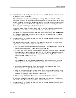
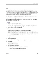
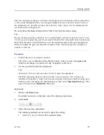
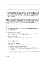
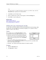
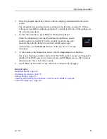
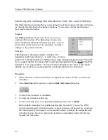
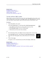
Open the button and select
Apply to all
if you wish to use the chosen setting in all the
views in the current presentation mode.
Related topics
Getting started, page 34
Starting normal operation, page 52
Tilt function, page 420
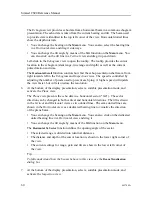
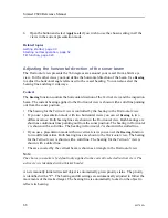
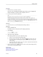
Adjusting the horizontal direction of the sonar beam
The
Horizontal
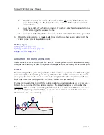
view presents the 360 degrees area around your vessel from a bird’s eye
view. For the other views you must define the horizontal direction of the beam. Use
Bearing
to adjust the horizontal angle referenced to the vessel heading. You can also select the
bearing line and drag it sideways.
Context
The
Bearing
function controls the horizontal direction of the
Vertical
view and the inspection
beam. The current bearing applied to the
Horizontal
view is shown with a solid line pointing
out from the sonar position.
• The bearing for the
Vertical
view is controlled by the bearing in the
Horizontal
view.
• If you use a presentation mode with two horizontal views you can set
Bearing
to two
different values. Both bearing lines are shown in the
Horizontal
view. Both bearings are
shown as continuous lines pointing out from the sonar position. The bearing in
Horizontal
1
is shown with a solid line. The bearing in
Horizontal 2
is shown with a dotted line.
• If you use a presentation mode with two vertical views you can set the
Bearing
function
to two different values. Both bearing lines are shown in the
Horizontal
view. The bearing
for the
Vertical
view is shown with a solid line. The bearing for the
Vertical 2
view is
shown with a dotted line.
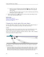
• The area covered by the vertical beam is shown as a triangle in the
Horizontal
view.
Note
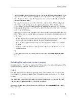
The choice you make is by default only applied to the currently selected (active) view. The
active view is identified with a thicker border.
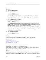
A new manually initiated tracked object is automatically given priority status. The priority
is identified with a "P". The bearing and tilt settings are automatically adjusted to follow the
movements of the tracked target. The bearing line is automatically locked on the object to
reflects its bearing.
Simrad CS90 Reference Manual
Summary of Contents for Simrad CS90
Page 1: ...kongsberg com simrad Simrad CS90 REFERENCE MANUAL ...
Page 2: ......
Page 627: ...442700 A 625 Related topics Concept descriptions page 622 Concept descriptions ...
Page 683: ......
Page 684: ... 2021 Kongsberg Maritime ISBN 978 82 8066 213 2 ...
Page 685: ......
Page 686: ...Reference Manual Simrad CS90 ...

