


TP-6196 10/09
96
Section 6 Component Testing and Adjustment
11. Connect and turn on the new fuel supply.
12. Check that the generator set master switch is in the
OFF position.
13. Reconnect the generator set engine starting
battery leads, negative (--) lead last.
14. Reconnect power to the battery charger.
15. Start the generator set by moving the generator set
master switch to the RUN position.
16. Check for leaks using a gas leak detector.
17. Move the generator set master switch to the AUTO
position.
To convert from LP vapor to natural gas, follow the same
fuel conversion procedure, moving the hose fitting to the
natural gas port and plugging the LP port.
For the
12kWmodel, disconnect the DSAI leads for LP vapor.
See Figure 6-37.
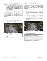
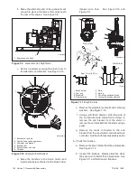
6.12.5 Digital Spark Advance Ignition
The digital spark advance ignition (DSAI) on the Model
12kWoptimizes the engine timing for the selected fuel,
natural gas or LP. The location of the DSAI leads is
shown in Figure 6-36. Connect the DSAI leads in the air
intake compartment together for natural gas fuel.
Disconnect the leads if LP is used. See Figure 6-37.
See the engine service manual for DSAI service
information.
6.12.6 Fuel Metering Valve Adjustment
The fuel system is factory-adjusted to comply with
applicable emission standards and to provide the best
possible hot and cold starting.
Note:
Adjusting the fuel metering valves on emissions-
certified generator sets may void the emission
certification.
Use a universal exhaust gas oxygen (UEGO) sensor to
check the fuel mixture after replacing the fuel regulator,
carburetor, or silencer. Use the following procedure to
check the fuel mixture after the engine has reached
normal operating temperature.
The fuel metering valves are sealed to prevent field
adjustments.
If the fuel metering valve requires
adjustment, do not break the seals on the fuel metering
valve.
Obtain a new fuel metering valve from the
manufacturer and replace the sealed valve with the new
part.
See Figure 6-36 for the fuel metering valve
location. Refer to the generator set Parts Catalog for the
fuel metering valve part number.
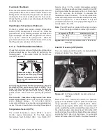
Only trained, authorized service technicians may adjust
the new fuel metering valve. The adjustment procedure
requires a digital volt meter (DVM), UEGO oxygen
sensor service kit GM29385, and a load bank capable of
the rated kW for the fuel being used. Always use an
oxygen sensor when adjusting the fuel metering valves.
Observe
the
following
safety
precautions
while
performing the procedure.
Hot engine and exhaust system.
Can cause severe injury or death.
Do not work on the generator set until
it cools.
WARNING
Servicing the exhaust system.
Hot parts can cause
severe injury or death.
Do not touch hot engine parts. The
engine and exhaust system components become extremely
hot during operation.
Fuel Mixture Check/Fuel Metering Valve
Adjustment Procedure
1. Place the generator set master switch in the OFF
position.
2. Disconnect power to the battery charger.
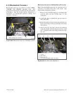
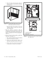
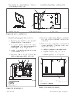
3. Remove the oxygen sensor plug from the exhaust
manifold and install the oxygen sensor.
See
Figure 6-38 for location.
1
GM29253
1. Oxygen sensor mounting location
Figure 6-38
Oxygen Sensor Mounting Location
Summary of Contents for 12RES
Page 2: ......
Page 6: ...TP 6196 10 09 6 Notes ...
Page 34: ...TP 6196 10 09 34 Section 3 Troubleshooting Notes ...
Page 52: ...TP 6196 10 09 52 Section 4 ADC 2100 and DC 2200 Controllers Notes ...
Page 72: ...TP 6196 10 09 72 Section 5 ADC RES and DC RET Controller Notes ...
Page 100: ...TP 6196 10 09 100 Section 6 Component Testing and Adjustment Notes ...
Page 131: ......


