


TP-6196 10/09
28
Section 3 Troubleshooting
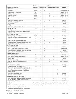
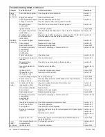
Troubleshooting Chart, continued
Problem
Possible Cause
Corrective Action
Reference
Generator
set does not
crank,
continued
Crank relay on relay
interface board
(ADC 2100)
Check connections to the RIB. Check for 12VDC to the RIB on
lead 71N.
Section 4.8 or
5.7; Section 8
Check for a good ground connection (lead 16N)
Section 8
Check crank relay K2 operation (LED3). Replace the RIB if relay
does not operate.
Section 4.8 or
5.7
Crank relay K3 on
controller circuit board
(ADC-RES)
Check connections to the controller.
Section 5.7
Section 8
Check for a good ground connection.
Section 8
Check LED3 to verify 12 VDC to relay K3.
If LED3 is not lit, check for 12 VDC to the board.
If LED3 is lit but the relay does not operate, replace the controller
circuit board.
Section 5.7
Blown fuse F2
(ADC-RES)
Replace fuse.
Section 6.13
If fuse blows again, disconnect the leads one at a time to identify
the cause of the blown fuse:
"
Lead 70C at the fuel valve.
"
Lead IGN at the ignition module
"
Lead 71A at the starter relay
"
Leads FP and FN at the rotor
"
Repair or replace the component causing the blown fuse.
Section 8,
ADV-7325
If fuse continues to blow and the previous step did not identify
the cause, check the continuity of leads FP and FN and the
leads from the P14 connector. Replace any bad leads. Use a
pin pusher to remove leads from the connector, if necessary. If
replacing the leads does not solve the problem, replace the
controller circuit board.
Section 8,
ADV-7325
Section 4.8 or
5.7
Generator set master
switch
Check connections to the master switch.
Section 6.15
Test function of master switch.
Section 6.15
Poor ground (--)
connection
Clean and retighten.
—
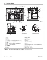
Starter relay
Check connections to the starter relay.
Section 1.7
Check continuity of circuit.
Section 6.15
Section 8
Check that the starter relay picks up when 12VDC is applied at
lead 71A connection.
Section 8
Starter
Check starter connections.
Section 1.7
Section 8
Rebuild or replace starter.
Engine Service
Manual (S/M)
Controller
Check controller connections and operation. Check for power to
the controller. Move generator set master switch to OFF/RESET
and then to RUN.
Section 4 or 5
Section 8
Cranks but
does not
start
No fuel
Open (turn on) manual fuel valve. Check fuel supply tank (LP).
—
Insufficient fuel pressure
Check fuel pressure to the generator set. Verify adequate fuel
pressure and pipe size for the generator set plus all other gas
appliances.
Section 6.12.3
Fuel regulator/valve
Check regulator/valve operation.
Section 6.12
4
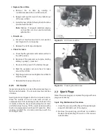
Spark plugs or spark
plug connections
Check spark plug wires and connections. Replace or clean and
regap spark plugs.
Section 2.3
Loose connection or
open circuit
Check for loose or open connection at the fuel valve (lead 70A)
and at the engine spark control module (leads IGN and 70A).
Check controller/engine wiring continuity.
Section 8
Summary of Contents for 12RES
Page 2: ......
Page 6: ...TP 6196 10 09 6 Notes ...
Page 34: ...TP 6196 10 09 34 Section 3 Troubleshooting Notes ...
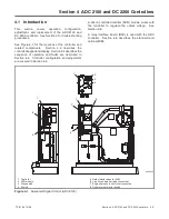
Page 52: ...TP 6196 10 09 52 Section 4 ADC 2100 and DC 2200 Controllers Notes ...
Page 72: ...TP 6196 10 09 72 Section 5 ADC RES and DC RET Controller Notes ...
Page 100: ...TP 6196 10 09 100 Section 6 Component Testing and Adjustment Notes ...
Page 131: ......


