


TP-6196 10/09
45
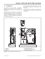
Section 4 ADC 2100 and DC 2200 Controllers
Display : *
or
To enter engine governor speed coarse adjustment
mode.
To raise or lower the engine speed in large
increments.
To enter engine governor stability (gain) coarse
adjustment mode.
To raise or lower the engine governor stability (gain)
in large increments.
To enter engine governor speed fine
adjustment mode.
To raise or lower the engine speed in smaller
increments.
To enter engine governor stability (gain) fine
adjustment mode.
To raise or lower the engine governor stability (gain)
in smaller increments.
4 P
4 P
or
or
or
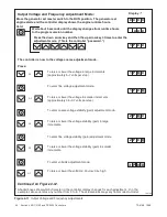
Continued from Figure 4-11:
Press:
5 P
5 P
* Shaded boxes show which character in the controller display changes for each adjustment.
X
in the
examples above denotes any number from 0 to 9. The actual values may vary from model-to-model.
S A V E
To enter SAVE mode. Go to Figure 4-13.
x x
x
x
x x
x
x
Note: Be sure to save your settings before exiting the configuration mode. The controller reverts to
the last
saved
settings when the master switch is moved to the OFF/RESET position.
Figure 4-12
Output Voltage and Frequency Adjustments, Continued
Summary of Contents for 12RES
Page 2: ......
Page 6: ...TP 6196 10 09 6 Notes ...
Page 34: ...TP 6196 10 09 34 Section 3 Troubleshooting Notes ...
Page 52: ...TP 6196 10 09 52 Section 4 ADC 2100 and DC 2200 Controllers Notes ...
Page 72: ...TP 6196 10 09 72 Section 5 ADC RES and DC RET Controller Notes ...
Page 100: ...TP 6196 10 09 100 Section 6 Component Testing and Adjustment Notes ...
Page 131: ......


