


TP-6196 10/09
32
Section 3 Troubleshooting
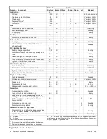
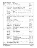
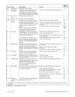
Troubleshooting Chart, continued
Problem
Reference
Corrective Action
Possible Cause
No output
voltage
AC output circuit breaker
open
Check for AC voltage on the generator side of circuit breaker. If
there is AC voltage on the generator side of the breaker, then a
problem in the load circuits is causing the line circuit breaker to
trip. Check for and correct short circuits or overloading on the
load side before resetting the circuit breaker.
—
Alternator or control
system
Perform separate excitation procedure to isolate the problem to
the alternator or the control system. Then troubleshoot the
alternator or control system components as follows.
Section 6.2
Aux. winding fuse F1
blown.
Check fuse F1 and replace if blown. If fuse blows again, check
stator.
Section 6.3
SCR module
Check auxiliary winding fuse F1.
Replace SCR module and test voltage.
Section 6.13
Section 6.8
Controller
Check controller settings. Check wiring and connections.
Before replacing controller, replace SCR module and check
voltage.
Section 4.5 or .
Section 6.8
Open wiring, terminal, or
pin in buildup circuit or
SCR module circuit
Check continuity.
Sections 6.13
Section 8
Brushes
Inspect brushes and replace if worn.
Section 6.6
Check for brushes sticking in brush holder or broken brush
spring.
Section 6.6
Rotor connections
Check for open circuit in rotor connection circuit (leads FN and
FP to SCR and RIB).
Section 8
Rotor slip rings dirty or
corroded
Check slip ring condition.
Section 6.4
Rotor (open, grounded,
or shorted windings)
Check voltage and continuity.
Section 6.4
Stator (open, grounded,
or shorted windings)
Check voltage and continuity.
Section 6.3
Flash relay (K3) on RIB
(ADC 2100)
Check flash LED on RIB.
Check fuse F2 and troubleshoot RIB.
Section 4.8
Flash relay (K3) on
controller board
(ADC-RES)
Check fuse F2.
Check flash LED1 on controller board. If LED1 indicates power
to K3 but relay does not operate, replace controller circuit board.
Section 5.7
Noisy
operation
Exhaust system leaks
Check and replace as necessary.
Section 2.6
Engine not running
smoothly
See
Generator set operates erratically
in this table.
—
Broken or damaged
vibromount(s)
Check and replace as necessary.
Section 7
Loose or vibrating sheet
metal/housing
Retighten screws, replace rivets.
—
Exhaust piping or air
inlets/outlets not
securely installed
Inspect for loose parts and secure if necessary.
Section 2.6
Excessive
engine/generator
vibration
Check, rotor, crankshaft, bearing, etc. (disassembly of engine
and/or alternator may be required).
Section 7
Engine S/M
Summary of Contents for 12RES
Page 2: ......
Page 6: ...TP 6196 10 09 6 Notes ...
Page 34: ...TP 6196 10 09 34 Section 3 Troubleshooting Notes ...
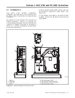
Page 52: ...TP 6196 10 09 52 Section 4 ADC 2100 and DC 2200 Controllers Notes ...
Page 72: ...TP 6196 10 09 72 Section 5 ADC RES and DC RET Controller Notes ...
Page 100: ...TP 6196 10 09 100 Section 6 Component Testing and Adjustment Notes ...
Page 131: ......


