


TP-6196 10/09
46
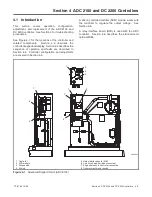
Section 4 ADC 2100 and DC 2200 Controllers
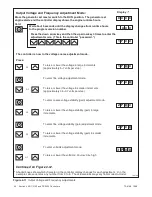
To save changes.
To discard changes without saving.
or
S A V E
Y E S
Now move the master switch to OFF/RESET.
n o
There are 3 options when the display says SAVE:
Press:
or
To return to the first parameter, coarse voltage adjustment, to check
or change settings before saving. See Figure 4-8.
“Yes”or “no” flashes when the up or down arrow is pressed and
then the controller exits the configuration mode. The display
returns to the runtime hours.
1 P
x x x x
x x
Figure 4-13
Save Mode (after generator set and engine adjustments)
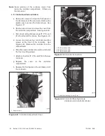
4.6 Continuous Power Mode
Jumper
Generator sets with serial numbers below 2051415
were built with controllers equipped with the continuous
power mode jumper.
See TT-1364, ADC 2100
Controller Replacement, for additional information.
Accidental starting.
Can cause severe injury or death.
Disconnect the battery cables before
working
on
the
generator
set.
Remove the negative (--) lead first
when disconnecting the battery.
Reconnect the negative (--) lead last
when reconnecting the battery.
WARNING
Disabling the generator set.
Accidental starting can
cause severe injury or death.
Before working on the
generator set or connected equipment, disable the generator
set as follows: (1) Move the generator set master switch to the
OFF position. (2) Disconnect the power to the battery charger.
(3) Remove the battery cables, negative (--) lead first.
Reconnect the negative (--) lead last when reconnecting the
battery. Follow these precautions to prevent starting of the
generator set by an automatic transfer switch, remote
start/stop switch, or engine start command from a remote
computer.
Short circuits.
Hazardous voltage/current can cause
severe injury or death.
Short circuits can cause bodily injury
and/or equipment damage
.
Do not contact electrical
connections with tools or jewelry while making adjustments or
repairs. Remove all jewelry before servicing the equipment.
Summary of Contents for 12RES
Page 2: ......
Page 6: ...TP 6196 10 09 6 Notes ...
Page 34: ...TP 6196 10 09 34 Section 3 Troubleshooting Notes ...
Page 52: ...TP 6196 10 09 52 Section 4 ADC 2100 and DC 2200 Controllers Notes ...
Page 72: ...TP 6196 10 09 72 Section 5 ADC RES and DC RET Controller Notes ...
Page 100: ...TP 6196 10 09 100 Section 6 Component Testing and Adjustment Notes ...
Page 131: ......


