


TP-6196 10/09
62
Section 5 ADC-RES and DC-RET Controller
5.6 Voltage and Frequency
Adjustments
Hazardous voltage.
Can cause severe injury or death.
Operate the generator set only when
all guards and electrical enclosures
are in place.
Moving parts.
WARNING
Short circuits.
Hazardous voltage/current can cause
severe injury or death.
Short circuits can cause bodily injury
and/or equipment damage
.
Do not contact electrical
connections with tools or jewelry while making adjustments or
repairs. Remove all jewelry before servicing the equipment.
Note:
The settings described in this section are not
adjustable on the DC-RET cotnroller.
The controller’s adjustment mode allows adjustment of
the output voltage and frequency, if necessary. Have
adjustments performed by an authorized distributor/
dealer or service technician. A digital multimeter that
measures voltage and frequency is required for these
adjustments.
The generator set must be running during voltage and
frequency adjustments.
Use a digital multimeter to
check the output voltage and frequency.
Refer to
Sections
6.7.2,
Voltage
Adjustment,
and
6.9.5,
Frequency Adjustment, for instructions to measure the
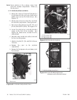
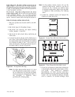
output voltage and frequency. Use the ADC controller to
adjust the output voltage and engine speed (frequency),
if necessary, while the generator set is running. See
Figure 5-9.
The flowcharts in Figure 5-13 through
Figure 5-15 outline the adjustment procedures.
Note:
Be sure to save your changes as instructed in
Figure 5-15 before exiting configuration mode.
Changes in voltage and frequency are lost if not saved
before the generator set shuts down. The generator set
continues to run with the new settings until it shuts down
but then reverts to the previous settings at the next
startup if the changes have not been saved.
5.6.1
Voltage Adjustment
Note:
Refer to the flowcharts in Figure 5-13 through
Figure 5-15 during the following procedure.
Voltage Adjustment Procedure
1. With the generator set off, connect a digital
multimeter to the output leads or an electrical outlet
on the load side of the generator set. Set the meter
to measure AC voltage.
2. Start the generator set by moving the generator set
master switch to the RUN position.
3. Use the ADC controller to adjust the voltage
(parameter 1P) until the output voltage reaches the
desired value.
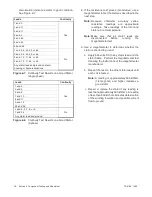
Refer to the flowcharts in
Figure 5-13 through Figure 5-15 for instructions to
adjust the output voltage. See Figure 5-11 for the
approximate change in voltage per step.
Measured
Voltage, VAC
ADC
Display
Voltage Change per
Step, VAC
Coarse
Fine
85--132
1P00--99
5
0.5
180--251
1P00--99
7
0.7
Figure 5-11
Voltage Adjustment (approximate)
4. Adjust the voltage stability (gain, parameter 2P) to
minimize light flicker.
5. Readjust the voltage, if necessary.
6. Set the multimeter to measure frequency.
7. Adjust the engine speed to the cut-in frequency
shown in Figure 5-12 by adjusting the engine
governor speed (parameter 4P).
Frequency
Cut-In Frequency
60 Hz
57.5 Hz
50 Hz
47.5 Hz
Figure 5-12
Cut-In Frequencies
8. Adjust the volts/Hz (parameter 3P) until the voltage
level measured by the multimeter begins to drop.
When the volts/Hz is set correctly, the generator
(as load is applied) attempts to maintain normal
output until the engine speed drops below the
cut-in frequency set in step 7.
Note:
See Section 6.7.3 for more information
about the volts/Hz (droop) adjustment.
Summary of Contents for 12RES
Page 2: ......
Page 6: ...TP 6196 10 09 6 Notes ...
Page 34: ...TP 6196 10 09 34 Section 3 Troubleshooting Notes ...
Page 52: ...TP 6196 10 09 52 Section 4 ADC 2100 and DC 2200 Controllers Notes ...
Page 72: ...TP 6196 10 09 72 Section 5 ADC RES and DC RET Controller Notes ...
Page 100: ...TP 6196 10 09 100 Section 6 Component Testing and Adjustment Notes ...
Page 131: ......


