


TP-6196 10/09
40
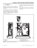
Section 4 ADC 2100 and DC 2200 Controllers
4.5 ADC 2100 Controller
Configuration and Adjustment
Note:
The settings described in this section are not
adjustable on the DC 2200 cotnroller.
The first step in troubleshooting the controller is to verify
that the controller is correctly configured for the
generator set.
The controller’s configuration modes
allow setting of the engine type, generator set
configuration (marine, mobile, or standby), data input
types, and other parameters.
The controller configuration for each generator model is
set at the factory.
Changes in the controller
configuration
may
be
required
after
controller
replacement or other service. Use the instructions in the
following section to check the controller settings and
change them, if necessary.
4.5.1
Controller Time Out
The controller will automatically exit the configuration
mode without saving any changes after about 1 minute
if no buttons are pressed.
Start the configuration
procedure again from the beginning if the controller exits
the configuration mode before the settings have been
saved.
Changes in voltage and speed adjustments are also lost
if they are not saved before the generator set shuts
down. The generator set continues to run with the new
settings until it shuts down but then reverts to the
previous settings at the next startup. Be sure to save
your changes immediately after making adjustments.
4.5.2
Controller Configuration
The controller configuration is factory-set and should
not normally require changes in the field. However, the
controller configuration may need to be checked or
changed during generator set service or controller
replacement.
The controller’s configuration mode allows adjustment
of the system parameters listed in this section. The
system voltage and frequency and unit configuration
and engine type are factory-set for each type of
generator set and engine and should not require
changes unless the controller is replaced.
The controller’s advanced configuration mode allows
the user to set the data input type for engine senders,
toggle the battery voltage between 12 and 24 volts, and
change the controller communications setting for
optional meters (not offered for standby models). Check
these settings after controller replacement and change
them, if necessary, to match the settings shown in
Figure 4-7.
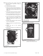
Follow the instructions in Figure 4-8 to enter the
configuration mode while the engine is not running and
then step through the following parameters. Use the up
(
∧
) and down
〈
∨
) arrow buttons to select the appropriate
setting for the application.
Note:
Be sure to save your settings before exiting the
configuration mode. The controller reverts to the
last saved settings when the master switch is
moved to the OFF/RESET position.
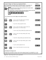
Voltage/frequency setting (Uu).
Select the system
voltage and frequency from the table in Figure 4-7.
Note:
This parameter sets the nominal system voltage
and frequency. To adjust the output (measured)
voltage and frequency, see Section 4.5.3,
Figure 4-11 and Figure 4-12.
Unit configuration (Uc).
This parameter sets the
generator set type: marine, standby, or mobile.
Engine configuration (Ec).
The engine configuration
must match the generator set engine type.
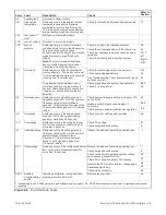
Parameter
Setting
Definition
Unit’s system voltage
and frequency.
Uu00
Single phase, 60 Hz, 120 VAC
Uu01 *
Single phase, 60 Hz, 120/240 VAC
Uu05
Single phase, 50 Hz, 115 VAC
Uu06 *
Single phase, 50 Hz, 115/230 VAC
Unit configuration
Uc01 *
Standby
Engine type
Ec00 *
8.5/12RES
Engine data input types
Ed05 *
Digital low coolant level, digital pressure, analog temp, with mag. pickup
Bt12 *
Battery voltage 12 VDC
Communications
Cn00 *
No CAN communications
* Factory settings. Choose 50 or 60 hz setting for Uu as required for generator set frequency .
Figure 4-7
ADC 2100 Controller Configuration Parameters
Summary of Contents for 12RES
Page 2: ......
Page 6: ...TP 6196 10 09 6 Notes ...
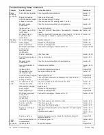
Page 34: ...TP 6196 10 09 34 Section 3 Troubleshooting Notes ...
Page 52: ...TP 6196 10 09 52 Section 4 ADC 2100 and DC 2200 Controllers Notes ...
Page 72: ...TP 6196 10 09 72 Section 5 ADC RES and DC RET Controller Notes ...
Page 100: ...TP 6196 10 09 100 Section 6 Component Testing and Adjustment Notes ...
Page 131: ......


