


TP-6196 10/09
79
Section 6 Component Testing and Adjustment
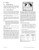
6.7 Voltage
6.7.1
Voltage Regulation
Voltage regulation is performed by the Advanced Digital
Control (ADC) and the SCR module. The ADC monitors
generator output voltage and adjusts the excitation
current to the rotor through the SCR module.
6.7.2
Voltage Adjustment
The factory sets the voltage for correct generator
operation under a variety of load conditions. Usually, the
voltage needs no further adjustment. Adjust the voltage
when necessary according to the following procedure.
The adjustment procedure requires a meter that can
measure voltage and frequency.
Use the ADC controller to adjust the voltage, gain, and
volts/Hz. Refer to Section4.5 for instructions to adjust
each setting and save the changes using the controller
keypad.
Note:
Be sure to save your settings as instructed. The
ADC controller will time out and exit the
adjustment mode after approximately 1 minute if
no buttons are pressed. Any unsaved changes
are discarded if the controller times out before the
settings are saved.
Voltage Adjustment.
Adjusts generator output
voltage.
Gain (Stability) Adjustment.
Fine tunes regulator
circuitry to reduce light flicker.
Volts/Hz Adjustment.
Determines frequency (Hz) at
which generator output voltage begins to drop. The
controller maintains generator output at the specified
voltage under load until the generator engine speed
drops to a preset level (factory setting 57.5 Hz on 60 Hz
models and 47.5 Hz on 50 Hz models).
Then the
controller allows the generator voltage and current to
drop. The voltage/current drop enables the engine to
pick up the load. When the generator speed returns to
normal (60 Hz or 50 Hz) as load is accepted, the
generator output also returns to normal. See Section for
more information about the volts/Hz (droop) adjustment.
Hazardous voltage.
Can cause severe injury or death.
Operate the generator set only when
all guards and electrical enclosures
are in place.
Moving parts.
WARNING
Short circuits.
Hazardous voltage/current can cause
severe injury or death.
Short circuits can cause bodily injury
and/or equipment damage
.
Do not contact electrical
connections with tools or jewelry while making adjustments or
repairs. Remove all jewelry before servicing the equipment.
Grounding electrical equipment. Hazardous voltage can
cause severe injury or death.
Electrocution is possible
whenever electricity is present. Ensure you comply with all
applicable codes and standards.
Electrically ground the
generator set, transfer switch, and related equipment and
electrical circuits. Turn off the main circuit breakers of all
power sources before servicing the equipment. Never contact
electrical leads or appliances when standing in water or on wet
ground because these conditions increase the risk of
electrocution.
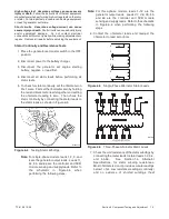
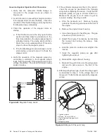
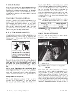
Voltage Adjustment Procedure
1. Connect a digital voltmeter from one side of the
circuit breaker to the L0 terminal inside the
controller assembly.
See Figure 6-12.
For
3-phase models. connect the voltmeter from L0 to
L1, L2, or L3 on the circuit breaker.
See
Figure 6-14. Set the meter to measure voltage.
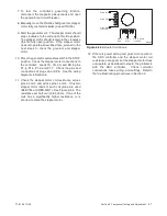
2. Start the generator set.
3. Follow the controller instructions in Section 4.5 to
enter the adjustment mode and increase voltage or
decrease voltage (parameter 1P) until the output
reaches the desired voltage. See Figure 6-11.
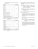
Models
Voltage
Measurement
Approximate
Voltage, VAC
1 phase, 60 Hz
L -- L0
120
L - L
240
1 phase, 50 Hz
L -- L0
115
L - L
230
3 phase, 50 Hz
L -- L0
230
L - L
400
Figure 6-11
Voltage Measurement
Summary of Contents for 12RES
Page 2: ......
Page 6: ...TP 6196 10 09 6 Notes ...
Page 34: ...TP 6196 10 09 34 Section 3 Troubleshooting Notes ...
Page 52: ...TP 6196 10 09 52 Section 4 ADC 2100 and DC 2200 Controllers Notes ...
Page 72: ...TP 6196 10 09 72 Section 5 ADC RES and DC RET Controller Notes ...
Page 100: ...TP 6196 10 09 100 Section 6 Component Testing and Adjustment Notes ...
Page 131: ......


