


TP-6196 10/09
71
Section 5 ADC-RES and DC-RET Controller
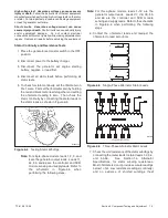
7. Check that the replacement board is positioned so
that the display shows through the opening in the
cover plate and then press the board onto the
standoffs.
Check that all corners are securely
mounted. See Figure 5-25.
8. Reconnect all cables and harnesses to the board.
See
the
wiring
diagram
in
Section 8
for
connections.
Note:
Connector P12 on the logic board is not
used at this time.
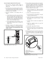
GM57149
1. User interface membrane
2. Controller logic board location
1
2
Figure 5-25
Controller
User Interface Membrane Replacement
9. Disconnect the membrane ribbon cable from
connector P8 on the logic board.
10. Carefully remove the membrane from the junction
box cover.
11. Remove the protective backing to expose the
adhesive on the new membrane.
12. Thread the new membrane’s ribbon cable through
the small rectangular opening in the cover. Line up
the membrane window with the larger rectangular
opening.
13. Press the membrane firmly into place.
14. Connect the ribbon cable to the P8 connector on
the logic board.
15. Verify that the generator set master switch is in the
OFF position.
16. Reconnect the engine starting battery, negative (--)
lead last.
17. Reconnect power to the battery charger.
18. Replace the front panel.
19. Check settings and adjustments for the ADC-RES
controller only:
a. Follow the instructions in Section 5.5.4 to
change the new controller’s configuration
settings to match the generator set system
voltage/frequency and unit configuration.
b. Use a voltmeter to check the output voltage.
Follow the instructions in Sections 4.5.3,
Voltage and Frequency Adjustments, and
6.7.2, Voltage Adjustment, to adjust the output
voltage and stability.
c. Check the output frequency.
Follow the
instructions in Sections 4.5.3, Voltage and
Frequency Adjustments, and 6.9.5, Frequency
Adjustment, to adjust the output frequency and
stability.
20. Place the generator set master switch in the AUTO
position if an ATS or remote start/stop switch is
used.
21. Replace the service door.
Summary of Contents for 12RES
Page 2: ......
Page 6: ...TP 6196 10 09 6 Notes ...
Page 34: ...TP 6196 10 09 34 Section 3 Troubleshooting Notes ...
Page 52: ...TP 6196 10 09 52 Section 4 ADC 2100 and DC 2200 Controllers Notes ...
Page 72: ...TP 6196 10 09 72 Section 5 ADC RES and DC RET Controller Notes ...
Page 100: ...TP 6196 10 09 100 Section 6 Component Testing and Adjustment Notes ...
Page 131: ......


