


TP-6196 10/09
66
Section 5 ADC-RES and DC-RET Controller
To save changes.
To discard changes without saving.
or
S A V E
Y E S
Now move the master switch to OFF/RESET.
n o
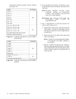
There are 3 options when the display says SAVE:
Press:
or
To return to the first parameter, coarse voltage adjustment, to check
or change settings before saving. See Figure 5-13.
“Yes”or “no” flashes when the up or down arrow is pressed and then the
controller exits the configuration mode. The display returns to the
runtime hours.
1 P
x x x x
x x
Figure 5-15
Save Mode
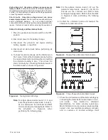
5.7 Controller Relays
The K1 flash, K2 fuel (run), and K3 crank relays are
located on the controller’s logic board.
An LED is
associated with each relay. See Figure 5-16.
The LED indicates power to the corresponding relay. If
the LED is illuminated but the relay is not activated, the
relay is faulty.
The individual relays are not replaceable. If one or more
relays are faulty, replace the logic board. LED 4 lights to
indicate a fault condition. See Section 4.4, Faults.
The controller board is protected by a 10-amp fuse (F2)
located on the controller. If the fuse blows repeatedly,
disconnect the board loads one at a time to identify the
cause of the blown fuse:
!
Lead 70C at the fuel valve
!
Lead IGN at the ignition module
!
Lead 71A at the starter relay
!
Leads FP and FN at the rotor
Repair or replace the component causing the blown
fuse.
If fuse continues to blow and disconnecting components
did not identify the cause, remove the leads from the
P14 connector using a pin pusher. If replacing the leads
does not solve the problem, replace the controller logic
board.
1. LED1 Flash (K1)
2. LED2 Fuel (K2)
3. LED3 Crank (K3)
4. LED4 Fault
5. LED5 SP2
6. LED6 SP1
1
GM49103
2
3
4
5
6
Figure 5-16
Relays and LEDs on Controller Logic
Board
Summary of Contents for 12RES
Page 2: ......
Page 6: ...TP 6196 10 09 6 Notes ...
Page 34: ...TP 6196 10 09 34 Section 3 Troubleshooting Notes ...
Page 52: ...TP 6196 10 09 52 Section 4 ADC 2100 and DC 2200 Controllers Notes ...
Page 72: ...TP 6196 10 09 72 Section 5 ADC RES and DC RET Controller Notes ...
Page 100: ...TP 6196 10 09 100 Section 6 Component Testing and Adjustment Notes ...
Page 131: ......


