


TP-6196 10/09
70
Section 5 ADC-RES and DC-RET Controller
5.9 Controller Replacement
If the troubleshooting procedures in Section 3 identify a
bad controller, use the procedure in this section for
controller replacement.
Always check the controller
configuration, fuse, wiring, and connections before
replacing the controller. For output voltage problems,
replace the SCR module and check the operation again
before replacing the controller.
After replacing the controller, verify that the new
controller’s configuration settings match the generator
set system voltage/frequency and unit configuration.
Refer to Section 4.5 for instructions to check the
controller configuration and to change the settings, if
necessary.
After the controller configuration has been checked and
set to match the generator set, use a voltmeter to check
the generator set output voltage and frequency. If the
output voltage or frequency needs adjustment, use the
voltage and frequency adjustment procedure in
Section 6.7.2 and the controller voltage and speed
adjustment instructions in Section 5.6. Also see the
frequency adjustment procedure in Section 6.9.5.
Hazardous voltage.
Will cause severe injury or death.
Disconnect all power sources before
opening the enclosure.
DANGER
Controller Replacement Procedure
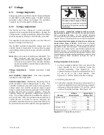
1. Remove the service door and the front panel to
access
the
controller
junction
box.
See
Figure 5-23.
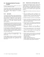
2. Place the generator set master switch in the OFF
position.
3. Disconnect power to the battery charger.
4. Disconnect the generator set engine starting
battery, negative (--) lead first.
ADV-7466C
1. Service-side door
2. Front panel
1
2
Figure 5-23
Enclosure Roof and Door
Logic Board Replacement
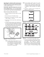
5. Note the connections on the logic board, and then
disconnect. See Figure 5-24.
6. Pull the old board straight off the mounting
standoffs.
fGM52541
1. P8 switch membrane connection
2. P9
3. P11 to engine harness and optional relay board, if equipped
4. P12 not used at this time
5. P1
6. P10
1
4
2
3
5
6
Figure 5-24
Controller Logic Board Connections
Summary of Contents for 12RES
Page 2: ......
Page 6: ...TP 6196 10 09 6 Notes ...
Page 34: ...TP 6196 10 09 34 Section 3 Troubleshooting Notes ...
Page 52: ...TP 6196 10 09 52 Section 4 ADC 2100 and DC 2200 Controllers Notes ...
Page 72: ...TP 6196 10 09 72 Section 5 ADC RES and DC RET Controller Notes ...
Page 100: ...TP 6196 10 09 100 Section 6 Component Testing and Adjustment Notes ...
Page 131: ......


