background image

HD Intelligent Speed Dome Camera 


                            User Manual 

38 


Picture 4-10 Dome camera 

1) 

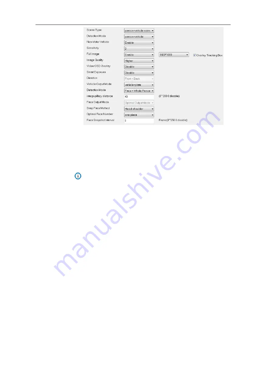
On  the  dropdown  list  of  “Scene  Type”,  select  a  detection  scene,  options  including 

“Person scene”, “Vehicle scene” and “ Vehicle scene”. 

2) 

On the dropdown list of “Detection Mode”, select a detection mode, options including 

“Person”, “Vehicle” and “ Vehicle”. 

Note: The configuration parameters of different detection modes are different. Please 

subject to the actual interfaces. This manual will take “ Vehicle” mode 

as an example. 

3) 

On the dropdown list of “Non-Motor Vehicle”, select “Enable” or “Disable” to output or 

not output non-motor vehicles. 

4)  Selec

t a level from the dropdown list of “Sensitivity”, the range being 1~5. The lower 

the sensitivity is, the lower the recognition rate and the false alarm rate there will be; 

and vice versa. 

5) 

Select  “Enable”  or  “Disable”  from  the  dropdown  list  of  “Full  Image”.  If  selecting 

“Enable”,  you  can  configure  the  resolution  of  panoramic  image.  Select  “Overlay 

Tracking  Box”  to  overlay  the  tracking  box  on  the  panoramic  image.  Select  a  level 

from  the  dropdown  list  of  “Image  Quality”.  Select  “Enable”  or  “Disable”  from  the 

dropdown list of “Video OSD Overlay”. If selecting “Enable”, the OSD will be overlaid 

on the panoramic image. 

6) 

Select “Enable” or “Disable” from the dropdown list of “Smart Exposure”. 

7) 

On the dropdown list of “Direction”, select “Front + Back”, “Front” or “Back” to filter 

the  output  targets  according  to  the  direction  (the  direction  facing  the  lens  is  front 

side). 


Select “Front + Back” to output detected targets in front and back directions. 


Select “Front” to output detected targets in front direction. 


Select 

“Back” to output detected targets in back direction. 

Summary of Contents for IPC425

Page 1: ...KEDACOM User Manual for HD Intelligent Speed Dome Camera V1 1 July 2020 ...

Page 2: ...reserved Without the prior written permission of Suzhou Keda Technology Co Ltd any reproduction translation or retransmission of all or any part of this document for any purpose in either electronic or mechanical form is not allowed Notice The information in this document is subject to change without notice Every effort has been made in the preparation of this document to ensure accuracy of the co...

Page 3: ...ns we shall not assume any responsibility Before installation please follow the instructions below Instructions 1 Please adopt power supply in the safety voltage range 2 If the product does not work properly please contact your dealer or the nearest service center Never attempt to disassemble or repair the product yourself in any way 3 Do not drop the camera or subject it to physical shock 4 When ...

Page 4: ...gineering must be carried out When installing it outdoor please note the following tips to reduce damage efficiently such as thunder 1 The distance between the signal wire and the high tension apparatus or high voltage cable should be at least 50m 2 Try to route cables along the eave when installing outdoor 3 When installing camera in an open field route cables inside sealed steel pipes under the ...

Page 5: ...ord Reset 13 2 5 Main Interface 13 2 6 Installation 14 2 6 1 Preset 14 2 6 2 Calibration 17 3 Basic Functions 20 3 1 Live View 20 3 1 1 PTZ Control 20 3 1 2 Preset 21 3 1 3 Image Adjustment 22 3 1 4 Live View Window 23 3 2 Playback 24 3 3 Snapshot 26 3 4 Local Setting 27 4 Intelligent 31 4 1 Intelligent Live View 31 4 2 Intelligent Settings 33 4 2 1 Path 33 4 2 2 DPSS 33 4 2 3 VIIAS 34 4 2 4 Guard...

Page 6: ...e 60 6 1 1 Image Adjustment 60 6 1 2 Exposure 60 6 1 3 Focus 61 6 1 4 White Balance 62 6 1 5 Night Cut 62 6 1 6 IR 64 6 1 7 Image Enhancement 64 6 1 8 Image Stabilization 65 6 1 9 Rotate and BNC 65 6 1 10 Effect Parameters 66 6 2 OSD 67 6 3 Video 68 6 3 1 Encoding Format 69 6 3 2 ROI 70 6 3 3 Privacy Mask 71 6 3 4 Video Info Overlay 72 6 4 Audio 72 6 4 1 Audio Encoding 72 6 4 2 Audio Decoding 73 6...

Page 7: ... Alarm Output 109 7 4 Abnormality Linkage 109 8 Storage 111 8 1 Storage Management 111 8 2 Recording 111 8 3 Snapshot 113 9 System 115 9 1 Device Info 115 9 2 User Security 115 9 2 1 User 115 9 2 2 RTSP Authorization 117 9 2 3 IP Filter 117 9 2 4 Security Service 117 9 3 Time 118 9 4 Serial Port 119 9 5 Log 120 9 5 1 Logs 120 9 5 2 System Health 120 9 5 3 Service Status 120 9 6 System Maintenance ...

Page 8: ...image flip and privacy mask Support multi stream to fit different network bandwidth Configurable text overlay on video image PTZ Functions Built in speed PT able to rotate continuously in pan and tilt support auto flip in tilt Support DOF proportional zooming auto watch last spot recovery PT restriction scheduled task mixed scan and etc Alarm Management Some with audio and alarm ports support talk...

Page 9: ...al 5 1 1 Product Appearance Picture 1 1 IPC425 series Picture 1 2 IPC445 series Picture 1 3 IPC489 series Note The appearances of different sub models may differ Please subject to actual devices 1 2 Applicable Scenarios Human Recognition Camera ...

Page 10: ...nt institutions school airport public security judiciary authorities and safe city General Recognition Camera The general recognition camera can capture independent snapshots of the target They are mainly used at places where people and vehicles are mixed together such as traffic lanes with people and vehicle taxi pick up and drop off spots bus stops tourist distribution center urban village inlet...

Page 11: ...Operating System Windows 7 or higher versions Browser Browser 32 bits 360 browser IE11 0 or newer Firefox 51 0 and lower versions Google Chrome 41 0 and lower versions DirectX 9 0 C Requirements of PC for installing the client of IPC489 series Processor CORE i5 7500 and higher Display Card HD 630 GPU or above RAM Memory 8GB or above Operating System Windows 7 or higher version Browser 32 bits 360 ...

Page 12: ...rd Click Activate Note When there are more than one non activated devices select the devices and click Batch processing On the popup interface set admin user s password and the email address to claim password Click Activate and wait for rebooting Picture 2 2 Batch Processing Activate through browser a Configure the IP addresses of PC in the same network segment as the camera and input the camera I...

Page 13: ...word periodically such as once every 3 months If the device is used in highly risky environment suggest modifying the password monthly or weekly Please keep your username and password safe 2 2 Quick Setting of Network Parameters After activating the device user can quickly modify the network parameters of the camera through IPCSearch including IP address subnet mask gateway and etc 1 Open IPCSearc...

Page 14: ...re 2 5 Reboot device Note To configure more parameters login to the web client and modify Please refer to Chapter 5 for details 2 3 Login and Log Out Login After activating the camera and modifying the parameters the device will reboot After reboot the button will be enabled again Select either of the following methods to login to the web client ...

Page 15: ...cessfully for the first time please download and install the plug in Close browser during installation After finishing re login to the web client Interface after login is shown below Attention Recommend IE kernel browser as other browsers may affect some functions of the client Picture 2 7 Web Client Interface Note After logging into the web client successfully for the first time the Quick Setting...

Page 16: ...cture 2 8 Quick setting interface Picture 2 9 Quick setting Log Out On the live view interface click to log out Help Click the icon at the top right corner of the window and the help file interface will pop up User can view the help file of the device ...

Page 17: ...link or scan the QR code in the above picture with a mobile device and fill in the Serial Number and Email address in the following picture Click Get Security Code Picture 2 11 Password Reset 3 Login to the email address to get a security code and fill in Command blank in Picture 2 10 and click OK Please remember the new password on the popup window and click OK The device will reboot 2 5 Main Int...

Page 18: ...his manual will take the general recognition camera to introduce the functions 2 6 1 Preset Go to Intelligent Settings Preset Setting and configure camera installation parameters Picture 2 12 Preset Configuration steps as follows 1 Select proper installation height for the camera according to the actual environment and the Quick Start Guide After finish installation adjust the camera to proper ang...

Page 19: ...s c Click icons of Zoom in or Zoom out to adjust the field of view and change the size of the calibration board or vehicle plate in the image when the calibration board coincides with the smaller frame it is the maximum scene when the calibration board coincides with the larger frame it is the minimum scene Pixel adjustment a Select Object Pixel Measure to show the interpupillary distance IPD of t...

Page 20: ...PD and finish adjustment of field of view 3 Focusing The default focus mode of the camera is auto Only when auto focusing cannot obtain clear images should user focus manually Note When the camera resolution is above 2 0 MP you need to edit the focus area manually You can arrange a person or put a richly textured object in the edit area so as to improve focus accuracy 1 Go to Settings Camera Image...

Page 21: ...igure calibration and prior area Note Calibration can be done only when the camera is installed If the camera height angle of pitch or focal length changes user needs to calibrate again Human recognition camera does not support Near Far Box Flag calibration Picture 2 17 Calibration 1 Select a preset number from the dropdown list 2 Calibrate When the camera is used to capture vehicle calibrate by r...

Page 22: ... 5 minutes 3 Configure prior area In actual conditions especially when the supplementary light in the field can only cover partial area it s necessary to configure prior areas When Enable Prior Area Flag is unselected the default prior area of the camera is full area after selecting Enable Prior Area Flag when an object enters the prior area the camera will output the optimum snapshots in this are...

Page 23: ...HD Intelligent Speed Dome Camera User Manual 19 Picture 2 19 Prior area 4 Click Save to validate settings and click Reset to reset setting ...

Page 24: ...s may have different functions and the disabled buttons on the web client means the device does not support the function Functions with in this manual means only some models support 3 1 Live View Click Live View to enter the preview interface Picture 3 1 Live View Click the hidden button on the left of the interface to hide PTZ control Preset and Image Adjustment interfaces Click it again to show ...

Page 25: ...bject is narrowed Buttons to adjust the sharpness of focused object Click to focus nearby object clear and distant object will become misty click to focus distant object and nearby object will become misty click to focus automatically Buttons to adjust the size of aperture Click to enlarge aperture and the image becomes bright click to narrow aperture and the image becomes dark click to adjust ape...

Page 26: ...Select a position and adjust lens direction and field of view to the requirements Then select a preset from the list and click the icon to save the position as a preset Delete Click this icon to delete a preset 3 1 3 Image Adjustment Click to show the following interface Picture 3 4 Image adjustment Adjust image brightness contrast saturation and sharpness if necessary by dragging the slide bars o...

Page 27: ...ratio of 16 9 means the live view window displays image in actual size 1 1 makes the image window adaptive to your PC resolution Stream Selection Main Stream Display the HD image It is the encoding format of live view and can be set in Settings Camera Video Encoding Format Secondary Stream Display the SD image It is the encoding format of live view and can be set in Settings Camera Video Encoding ...

Page 28: ... The pixels of this area will be amplified and will cover the whole screen Left click and drag toward upper left to draw an area then the image will recover Double click a point in the image and the point will be centered Status click this button to display the frame rate and bitrate of the live video and click again to hide This button is hidden by default To enable this function go to Settings L...

Page 29: ...playback user can perform operations such as clipping accelerating and downloading the video recording 4 Put the cursor of the mouse on the timeline to show the time of the video Double click or press the left button of the mouse and drag the timeline to skip playing Also user can set playback time under Go To and click to select playback time Buttons on the playback interface Icon Note Play Pause...

Page 30: ...ocal Setting Download click the icon to pop up the download interface On the popup interface configure the start time end time and select video type s to download Click Search to display expected videos Select the files to be downloaded and click Download User can view the download progress on the list Save path can be set in Chapter 3 4 Settings Local Setting Zoom in Zoom out timeline adjust the ...

Page 31: ...End Time 3 Click Search and the search result will show on the right list from which you can see picture ID and snapshot time 4 Select pictures and click to download the selected pictures Snapshot save path can be set in Local Setting Camera Snapshot Save Path 3 4 Local Setting Go to Settings Local Setting and configure parameters of video playing the size and save path of video records and snapsh...

Page 32: ... video smooth ensures smooth playing of the video but affects the real time performance of the video Decoded Process Mode Select the process mode after decoding options including Default and Brightness Enhance Enable Image Noise Reduction After selecting it drag the slide bar below to adjust the noise reduction level including 4 levels Enabling image noise reduction will change the resolution of c...

Page 33: ...ck Opendir to open the folder where the clippings are saved currently Download Save Path Configure the local save path for recordings downloaded during playback Click the button of View to customize the save path Click Opendir to open the folder where the recordings are saved currently Snapshot Local Snapshot Save Path Configure the local save path for snapshots captured during live viewing Click ...

Page 34: ...e button of Download Plug in to download the video plug in When logging into the web client for the first time download and install the plug in to view the live video normally Note Please follow the Quick Start Guide strictly during installation ensure the normal working of functions such as preset loading and path patrol ...

Page 35: ...according to configurations and display the qualified snapshots in New Snapshot area click this button again to disable capturing function and hide snapshots Go to Intelligent Settings Parameters to configure the parameters and click Save to validate setting Open directory of snapshot Click this button to open the file folder of snapshots from local PC Video recording Click this button to start vi...

Page 36: ...snapshots and snapshot display Picture 4 2 Capture and display optimal snapshot or not Real time statistics It shows the real time statistic information on the top of the live view window including people sum vehicle sum and non motor vehicle sum and the target sum of different directions New Snapshot It shows the snapshot result of latest person vehicle or non motor vehicle including target close...

Page 37: ...lligent Settings Path to configure save path of snapshots Picture 4 5 Path setting Configuration steps are as follows 1 Click Browse on the right and select the local path for saving snapshots and click OK 2 Click Save to validate setting click Reset to restore default path 4 2 2 DPSS The camera obtains the MAC address of wireless front end device such as a cellphone through Wi Fi and transfers th...

Page 38: ...AS access function 4 Enter ID of device to access to the VIIAS platform 5 Enter IP address and port number of VIIAS platform 6 Enter user name and password of VIIAS platform 7 Enter heartbeat signaling interval Note The heartbeat signaling interval is used to detect TCP disconnection Usually it sends simple communication packets periodically If the system does not receive any response from the oth...

Page 39: ...nd shield area in the image so as to configure key snapshot area and uninterested area Note Go to Intelligent Settings Custom Setting Arming select Disable and click Save After the setting takes effect guard area can be configured Picture 4 8 Guard area setting Guard Area After configuring guard area the system will lock any moving targets such as people vehicles or non motor vehicles entering the...

Page 40: ...Add to add guard area or face guard area or shield area and left click on the image to select 3 20 vertexes and right click to form a closed area 4 After editing click Save and the guard area or face guard area or shield area will be added successfully 5 After finishing configuration of the guard area perform arming configuration to realize the purpose of excluding interference Go to Intelligent S...

Page 41: ...and captures and analyzes people vehicles and non motor vehicles entering the guard areas Configuration steps are as follows a Select All or weekdays one by one b Set the start time From and end time to c Click Add and the arming duration will display in the box Select the added duration and click Delete to delete the duration d Repeat the above steps to configure different arming durations 3 Clic...

Page 42: ...e lower the recognition rate and the false alarm rate there will be and vice versa 5 Select Enable or Disable from the dropdown list of Full Image If selecting Enable you can configure the resolution of panoramic image Select Overlay Tracking Box to overlay the tracking box on the panoramic image Select a level from the dropdown list of Image Quality Select Enable or Disable from the dropdown list...

Page 43: ...ap Face Method Optimal Face Number and Face Snapshot Interval If selecting Face or Face Whole Person the Face Output Mode can be Optimal Output Mode or Continuous Output Mode The default Optimal Face Number is 1 or you can select Several pieces Options for Snap Face Method include head shoulder upper body and upper shoulder Configure Interpupillary Distance by actual condition Face Snapshot Interv...

Page 44: ...ing to actual request Region Code Select the default region of plate according to actual request Attribute Select vehicle attributes according to actual request including sun visor driver face vehicle logo vehicle type calling and etc After finishing configuration click Save to validate settings Click Reset to restore to default configurations 4 2 8 Patrol Patrol means the camera patrols among eac...

Page 45: ...configuration Select Enable and when the panoramic image on the dome camera interface is enabled the OSD text will be overlaid on the panoramic image 1 Go to Intelligent Settings OSD Picture 4 13 OSD setting 2 Select Enable to enable OSD on vehicle panoramic image 3 Select a position where the OSD will display 4 Select a time format from the dropdown list of Time Format 5 Select a color from the d...

Page 46: ...ngs Protocol Setting Picture 4 14 Protocol setting 2 Select a platform from the dropdown list of Platform 3 Select Enable to enable platform service 4 Enter platform IP address and port number 5 Select a data transmission protocol from the dropdown list of Protocol 6 Select data to upload to the platform 7 Enter UUID address and platform user name and password 8 Configure data upload directory by ...

Page 47: ...de and outside brightness under scheduled mode as the LED fill light is enabled in scheduled duration configure LED start time end time and LED inside and outside brightness Note The Threshold parameter is configurable under Auto mode only the Start Time and End Time are configurable under Scheduled mode only 3 Click Save to validate setting Click Reset to restore to default values 4 2 12 Event Se...

Page 48: ...ecessary to output alarm audio the camera needs to connect to a loudspeaker or a voice box which means to connect the wire Audio Out and GND to the loudspeaker or voice box For wire connection please refer to the Quick Start Guide Note Go to Settings System System Maintenance and click Configuration to enter advanced configuration interface and configure Minimum Alarming Interval The default value...

Page 49: ...ber of people is equal to or more than X The camera starts alarming once it detects target entering the configured guard area and will stop alarming till the target leaves the guard area 4 2 13 Version Go to Intelligent Settings Version to view Web Plugin Version IPC APP Version and Algorithm Version Picture 4 17 Version ...

Page 50: ... need to configure IP Address Subnet Mask and Default Gateway manually when selecting DHCP mode the system obtains IP address automatically Note When filling the IPV4 IP address click Test to confirm if the address is available If selecting IPV6 the mode includes Manual and Automatically obtain Under the Automatically obtain mode the IPV6 address is distributed from server gateway or router Under ...

Page 51: ...behind camera IP address For example if HTTP port is edited as 83 when you login through browser you need to input http camera IP address 83 The number is 80 by default ranging 1 65535 HTTPS Port Hypertext Transport Protocol Secure Port based on SSL When login through browser you need to add a port number behind camera IP address For example if HTTPS port is edited as 5545 when you login through b...

Page 52: ...The source host can send the data packets to every host in the group by sending a datagram only It also depends on the group relationship maintenance and selection by the router Picture 5 4 Multicast Stream Type the stream to be sent the default being Main Stream Media Type the media type of the stream to be sent the default being Video Multicast Address the address to send the stream fill it acco...

Page 53: ... 5 2 1 VSIP The web client supports accessing to back end platform through VSIP protocol Configuration steps 1 Go to Settings Network Access Protocol VSIP Picture 5 5 VSIP 2 Enter VMS IP address or domain name 3 Enter VMS Port Number default being 5510 4 Enter Camera UUID and Camera Password Camera UUID is distributed by VMS and the password needs no verification so you don t have to enter 5 When ...

Page 54: ...ate a server address URL automatically default port number being 80 3 Set authentication method for ONVIF login When selecting N A user can login freely when selecting WS Username token user needs to verify username and password before login 4 Click Save to validate settings 5 2 3 SIP On SIP interface add the camera to GB platform according to the requirements of GB T28181 Configuration steps are ...

Page 55: ...mera User Manual 51 Picture 5 7 SIP 5 2 4 VIID The camera can upload the captured snapshots to VIID platform for future data analysis and comparison Configuration steps are as follows 1 Go to Settings Network Access Protocol VIID ...

Page 56: ...unication packets periodically If the system does not receive any response from the other side in the configured interval it will judge the other side has been disconnected For example if the parameter is set 30 the system will send the packet once every 30 s 7 Enter installation address and regionalism if necessary for facilitating device positioning 8 Click Save to validate settings 5 2 5 PDNS W...

Page 57: ...hrough servers Apply domain names at different server websites and then visit the device by domain names directly even if the IP address has been modified Configuration steps are as follows 1 Go to Settings Network Other Protocols DDNS Picture 5 10 DDNS 2 Select Enable 3 Select DDNS Server type from the dropdown list options including ORAY DYNDS and NOIP When selecting DYNDS or NOIP the domain nam...

Page 58: ...e directory options include Use device name Use device IP and Custom Level two directory options include Use channel number and Custom 5 Click Test to verify if current FTP is available and the result will show on the dialogue box 6 Select Upload pictures if necessary 7 Click Save to validate setting 5 3 3 PPPoE PPPoE Point to Point Protocol over Ethernet function is to access camera to the intern...

Page 59: ...tion Threshold and Packet Loss Rate Threshold The default values are all 100 ranging 1 100 4 Click Save to validate setting 5 3 5 802 1X 802 1X is a port based network access control protocol User can select Protocol Type manually to control if the device connected to the LAN can access to the LAN which will support the requirements of network authentication charging safety and management well Con...

Page 60: ...ect and keep packets according to their priority levels Different levels occupy different bandwidths with different packet loss rates during network congestion thus the quality of service is ensured Attention You need to configure the same value on the router 4 Click Save to validate setting 5 3 7 UPnP By UPnP protocol it is able to set up mapping relation between private network and the internet ...

Page 61: ... for user to visit current IP address 4 Select Auto or Manual for Mapping Mode When selecting Manual enter external port number manually 5 Click Save to validate setting 5 3 8 SNMP SNMP means Simple Network Management Protocol It is an application level protocol consisting of a set of network management standards that support a network management system for monitoring devices connected to the netw...

Page 62: ... Password Encryption Mode and Encryption Password 8 Click Save to validate settings 5 3 9 SMTP SMTP means Simple Message Transfer Protocol When an alarm is triggered the system will send email notification automatically through SMTP protocol Configuration steps are as follows 1 Go to Settings Network Other Protocols SMTP Picture 5 18 SMTP 2 Input SMTP server IP address and port number which ranges...

Page 63: ...ddress from the list and click the symbol to remove the email address 6 Click Save to validate setting Note After finishing configuration and enabling email notification it will send alarm emails normally 5 4 Cloud Service Go to Settings Network Cloud to enable cloud service and install KEDACOM App on mobile devices User can view live video on mobile devices through the App Picture 5 19 Cloud serv...

Page 64: ...stment exposure focus and etc Picture 6 1 Image 6 1 1 Image Adjustment Picture 6 2 Image adjustment The image adjustment in this part is the same as that on the Live View interface which can be referred to in Chapter 3 of Image Adjustment 6 1 2 Exposure Picture 6 3 Exposure Gain A higher gain will make the image look brighter However meanwhile there will be more noise points on the image Auto mode...

Page 65: ... Manual Suggest Auto When selecting Auto you can select Shutter Lower Threshold from the dropdown list below Then the shutter will be adjusted within the range from the lower threshold to the minimum shutter value automatically When selecting Manual you can select Shutter Level from the dropdown list below Then the value of shutter will remain Anti flicker When there are floating cross stripes on ...

Page 66: ...rature of the light source Picture 6 5 White Balance Select an option from the dropdown list of white balance mode Suggest Auto Manual support R Gain and B Gain adjustment Auto 2 have a larger white balance range than Auto 1 though both are auto mode Lock White Balance lock current color correction matrix If the camera works under light which provides fixed light condition select according to actu...

Page 67: ...nsor triggered The camera detects light strength and triggers night cut according to the returned value When selecting this mode configure Photosensitivity Latency and Night Cut Threshold according to actual request Photosensitivity The switching sensitivity from night mode to day mode The lower the sensitivity is the higher brightness in the condition the camera needs to switch to day mode the hi...

Page 68: ...Noise Reduction You can select Enable or Disable After enabling you can drag the slide bar to adjust 2D noise reduction level 3D Noise Reduction You can select Enable or Disable After enabling you can drag the slide bar to adjust 3D noise reduction level Note When the 3D noise reduction level is too high there will be hauling tail on moving objects Usually it s unnecessary to edit this parameter D...

Page 69: ...ile the latter being too dark Select WDR from the drop down list of Dynamic Adjustment and drag the slide bar of WDR Sensitivity Auto WDR The camera will adjust exposure automatically according to the light conditions Image Enhancement When there is fog in the scene select Gamma or Defog from the dropdown list to enable image enhancement and drag the slide bar to adjust the sensitivity Distortion ...

Page 70: ...t parameters Auto Mode Select Auto Mode and configure the switch conditions on the popup interface options including Night Cut and Time Schedule If selecting the former configure day scene mode and night scene mode if selecting the latter configure the start time and end time of switching Picture 6 13 Auto mode Standard Mode Select Standard Mode and all parameters will restore to defaults Indoor M...

Page 71: ...ure 6 14 OSD 2 Select options in Content according to requirements and preview the effect in the window below options including Time Label Alarm PTZ and OSD 3 Click Advanced to set Format Font and Margin In format you can set Time Format Display time in 2 lines and Alarm in front of tag In font you can set font Type Size and Color In margin you can adjust the distance between OSD border and image ...

Page 72: ...ue box and the light blue box can move freely in the yellow box and they can even overlap with each other The time label and alarm OSDs in the dark blue box move with the box while the custom OSDs and PTZ OSD in the light blue box move freely in the light blue box and the light blue box can be downsized within the yellow box up to actual request Note The OSD box size changes with the font size and...

Page 73: ...ream by average bitrate with high speed compressing but there may be mosaic on the images while VBR adjusts bitrate automatically with slow compressing but could ensure image sharpness under complex conditions Image Quality When selecting VBR select image quality level from the dropdown list according to actual requirements The higher the level is the clearer the image will look Frame Rate Set the...

Page 74: ...in Middle when CBR is selected Different encoding formats have different levels of encoding complexity The higher the Encoding Complexity is the more the stream will be compressed In this way it will relieve bandwidth restriction somehow but meanwhile it will also occupy the CPU resource of more devices Suggest using the default level After enabling Smart Encoding some functions will be disabled s...

Page 75: ...Privacy mask 2 Select Enable to enable privacy mask 3 Click Edit and the image is divided into 16 columns and 12 rows of small squares Click any square and drag an area toward lower right then this area is the privacy mask detection area Click Clear to reset the area 4 Select a color from the dropdown list of Mask Color 5 Configure arming duration The default arming duration is 24 hours in blue ba...

Page 76: ... Click Save to validate the settings 6 3 4 Video Info Overlay Go to Settings Camera Video Video Info Overlay and composite basic intelligent feature and digital watermarking into the surveillance image Picture 6 21 Video info overlay GPS Select it to show camera coordinates in the image Lens Direction Select it to show lens direction in the image Basic Intelligent Feature After configuring intelli...

Page 77: ...ncellation Select the checkbox to cancel noises in the input audio and to improve the audio quality Click Save to validate settings 6 4 2 Audio Decoding Go to Settings Camera Audio Audio Decoding and configure audio decoding Picture 6 23 Audio decoding Audio Decoding Setting Decoding Volume i e audio output volume drag the slide bar to adjust audio decoding volume Audio Mixing Recording Select the...

Page 78: ...n the following picture Picture 6 24 Basic Configuration Basic Config PT Version Display the version of current PT Patrol Speed Level The patrol speed level of the PTZ holder The larger the value is the faster it patrols vice versa Preset Point Speed Level The speed level of loading presets The larger the value is the faster the PTZ holder will rotate to the preset vice versa Zoom Speed Level The ...

Page 79: ...position before powering off automatically when it is powered again Configure recovery time If selecting Load Preset When Power On the PT will load to the selected preset directly Configure preset No 3 Recovery Time Configure the recovery time when the power is off ranging 30 360s by default 60s Note When the time the PT stops at a position before powering off exceeds the set Recovery Time it will...

Page 80: ...the patrol path is selectable Please refer to chapter 6 5 5 for configuration steps Frame Mode In every key frame interval camera rotates frame by frame by 90 automatically in pan direction The Waiting Time is configurable Random Mode Camera patrols at random speed in pan direction The Waiting Time is configurable Panoramic Mode Camera patrols panoramically in tilt and pan The Waiting Time is conf...

Page 81: ...te to remove the preset and Delete All to delete all presets 7 In the preset part of the Live View interface user can also select a preset to load save or delete Details can be referred to in chapter 3 1 2 Note Click the events behind Related Alarm to skip to the intelligent function interfaces 6 5 4 Restricted Patrol Restricted Patrol includes Manual and Auto modes After enabling this function us...

Page 82: ...abling auto mode the PTZ will patrol horizontally only between the left top and the right bottom limits 6 5 5 Path Mode Path Mode means the camera patrols around all the valid presets on a path After enabling this function click any button on PTZ control to disable it Currently the camera supports 8 paths and the maximum allowed number of patrol spots on each path is 32 Configuration steps are as ...

Page 83: ...dropdown list of Patrol Path 3 Click Start recording and adjust PTZ position to record PTZ rotation steps and zooming operations click Stop recording to stop recording The maximum length of each path is 10 minutes 4 Click Preview to preview all PTZ operations 5 Click Stop to stop previewing 6 Select path and click Delete records to delete all recorded PTZ operations under this path 7 Click Delete ...

Page 84: ...task duration on that day b Click the duration and a window will pop up for editing the scheduled task Select the scheduled task from the dropdown list Or you can edit the start time and end time otherwise Click Save to finish configuration of scheduled task c Click any free point on the timeline and configure the next duration Different durations cannot overlap d Click the icon behind the timelin...

Page 85: ... the location of the camera including its pan tilt zero correction and positioning User can perform the following configurations Picture 6 33 Positioning Compass Setting Direction Calibration Click Direction Calibration and the device will calibrate automatically and face north when finishes calibration Pointing Northward After finishing direction calibration click Pointing Northward and the devic...

Page 86: ...ates show the coordinates of current PTZ position Horizontal Coordinate fill the target horizontal coordinate and click Horizontal Positioning then the PTZ will rotate to the target pan position Vertical Coordinate fill the target vertical coordinate and click Vertical Positioning then the PTZ will rotate to the target tilt position Azimuth Positioning it means the PTZ camera faces to the due nort...

Page 87: ...is chapter will introduce the configuration steps of each event 7 1 1 Motion Detection Motion detection is to detect if there is any moving object in specific areas during certain periods of time Once the moving object exceeds the defined sensitivity the system will start video recording or trigger an alarm according to the linkage method set by user Configuration steps are as follows 1 Go to Sett...

Page 88: ...bar to adjust the Sensitivity of motion detection The higher the sensitivity is the easier it will trigger an alarm 5 Click Edit and it will pop up a window for configuring PTZ linkage Picture 7 2 PTZ linkage PTZ Rotation Stops Detection Configure the waiting time after PTZ holder stops moving i e after the PTZ stops moving for the configured duration it will start detection Motion Detection Effec...

Page 89: ...and end time Copy duration click the copy icon behind the timeline and copy the durations on the day to one or several other days Delete duration click Delete All above the timeline to delete all the durations Select any duration and click Delete on the popup window or above the timeline to delete the duration Note Select any duration with a mouse and drag the blue bar on the timeline as a whole w...

Page 90: ...columns and 12 lines of small squares Click a square drag toward lower right and click Stop Then the area is the detected area and it turns purple red A camera can support max 1 video blocked area at the same time 4 Drag the slide bar to adjust Sensitivity the higher the sensitivity is the easier it will trigger an alarm 5 Select linkage type s which is are the alarm output method s when video blo...

Page 91: ...ct the timeline of any day and delete the default blue bar Left click on the mouse and drag on the timeline from left to right to form a blue bar above which it shows the start time and end time Copy duration click the copy icon behind the timeline and copy the durations on the day to one or several other days Delete duration click Delete All above the timeline to delete all the durations Select a...

Page 92: ... the preset with the guard line alarming 4 Select a program from the dropdown list of Programme Note One program can configure one guard area only and one area is allowed to edit only one guard line After saving the guard line user can configure other guard lines It supports maximum 4 guard lines 5 Select a number from the dropdown list of Associated Preset Bits ...

Page 93: ...guard line s 8 Area Setting to set guard lines Click Edit and drag the mouse in the scene to draw a guard line User can click its starting or end point to adjust its length and angle click Stop to stop editing 9 Drag the slide bar of Sensitivity to set the guard line s sensitivity to moving objects the higher the sensitivity is the easier it will trigger an alarm 10 Select linkage type s which is ...

Page 94: ...elete All above the timeline to delete all the durations Select any duration and click Delete on the popup window or above the timeline to delete the duration Note Select any duration with a mouse and drag the blue bar on the timeline as a whole without changing the length of recording duration 12 Click Save to validate settings 7 1 4 Entry Guard Area The function is to detect if there is anything...

Page 95: ...ink the preset with the guard line alarming 4 Select a program from the dropdown list of Programme Note One program can configure one guard area only and one area is allowed to edit only one guard line After saving the guard line user can configure other guard lines It supports maximum 4 guard lines 5 Select a number from the dropdown list of Associated Preset Bits ...

Page 96: ...l trigger an alarm 9 Select linkage type s which is are the alarm output method s when an event triggers an alarm 10 Set arming duration the default is 24 hours displaying in blue bar or user can customize durations The maximum allowed number of durations is 10 on one day and different durations cannot overlap with each other Picture 7 9 Arming durations Set duration configure arming durations acc...

Page 97: ...any duration with a mouse and drag the blue bar on the timeline as a whole without changing the length of recording duration 11 Click Save to validate settings 7 1 5 Exit Guard Area The function is to detect if there is anything leaving the set guard area and the camera will judge if it is necessary to trigger an alarm Configuration steps are as follows 1 Go to Settings Event Intelligent Function ...

Page 98: ...e mouse in the scene to draw a rectangle Click Stop after finishing and drag the slide bar of Max and Min Target Ratio 1 by default Moving objects over max or below min will not trigger an alarm when they enter the guard area s 7 Area Setting to set guard area Click Edit and click mouse to draw a closed area made up of 3 to 6 points in the scene Right click or click the starting or ending point to...

Page 99: ...py icon behind the timeline and copy the durations on the day to one or several other days Delete duration click Delete All above the timeline to delete all the durations Select any duration and click Delete on the popup window or above the timeline to delete the duration Note Select any duration with a mouse and drag the blue bar on the timeline as a whole without changing the length of recording...

Page 100: ...ink the preset with the guard line alarming 4 Select a program from the dropdown list of Programme Note One program can configure one guard area only and one area is allowed to edit only one guard line After saving the guard line user can configure other guard lines It supports maximum 4 guard lines 5 Select a number from the dropdown list of Associated Preset Bits ...

Page 101: ...d i e the maximum allowed time for the object to stay in the area For example if it is set 5 s when there is an object entering the guard area and stays for 5 s it will trigger an alarm 10 Select linkage type s which is are the alarm output method s when an event triggers an alarm 11 Set arming duration the default is 24 hours displaying in blue bar or user can customize durations The maximum allo...

Page 102: ... timeline to delete the duration Note Select any duration with a mouse and drag the blue bar on the timeline as a whole without changing the length of recording duration 12 Click Save to validate settings 7 1 7 Object Left The function is to detect if there is any object being left in the set guard area and staying for a period of time reaching the set threshold The camera will judge if it is nece...

Page 103: ...target area Click Edit and drag the mouse in the scene to draw a rectangle Click Stop after finishing and drag the slide bar of Max and Min Target Ratio 1 by default Moving objects over max or below min will not trigger an alarm when they enter the guard area s 5 Area Setting to set guard area Click Edit and click mouse to draw a closed area made up of 3 to 6 points in the scene Right click or cli...

Page 104: ...al requirements Click the blue bar to pop up a window for editing the accurate start time and end time click Save to validate setting Click any duration and there will be small white squares on the 2 ends of it Put the mouse on any whit square left click and drag the edit the start time and end time Select the timeline of any day and delete the default blue bar Left click on the mouse and drag on ...

Page 105: ...time threshold The camera will judge if it is necessary to trigger an alarm Configuration steps are as follows 1 Go to Settings Event Intelligent Function Object Removal Picture 7 16 Object removal 2 Select Enable 3 Select a number from the dropdown list of Guard Area and user can set only one area at one time After saving it user can set another and max 4 areas can be set ...

Page 106: ...s when an event triggers an alarm 9 Set arming duration the default is 24 hours displaying in blue bar or user can customize durations The maximum allowed number of durations is 10 on one day and different durations cannot overlap with each other Picture 7 17 Arming durations Set duration configure arming durations according to actual requirements Click the blue bar to pop up a window for editing ...

Page 107: ...to validate settings 7 1 9 Gathering When the coverage of people in the guard area exceeds a set ratio the camera will judge if it is necessary to trigger an alarm For example if the ratio is set 50 when 50 or more of the area is covered by people an alarm will be triggered Configuration steps are as follows 1 Go to Settings Event Intelligent Function Gathering Picture 7 18 Gathering 2 Select Enab...

Page 108: ...ed area made up of 3 to 6 points in the scene Right click or click the starting or end point to close the area and click Stop to finish 8 Select linkage type s which is are the alarm output method s when an event triggers an alarm 9 Set arming duration the default is 24 hours displaying in blue bar or user can customize durations The maximum allowed number of durations is 10 on one day and differe...

Page 109: ...click Delete on the popup window or above the timeline to delete the duration Note Select any duration with a mouse and drag the blue bar on the timeline as a whole without changing the length of recording duration 10 Click Save to validate settings 7 1 10 Audio Surge When there is audio surge the camera will judge if it is necessary to trigger an alarm Configuration steps are as follows 1 Go to S...

Page 110: ...to pop up a window for editing the accurate start time and end time click Save to validate setting Click any duration and there will be small white squares on the 2 ends of it Put the mouse on any whit square left click and drag the edit the start time and end time Select the timeline of any day and delete the default blue bar Left click on the mouse and drag on the timeline from left to right to ...

Page 111: ...evices and the camera will judge by the received alarm signal if it is necessary to trigger an alarm Configuration steps are as follows 1 Go to Settings Event Alarm Input Picture 7 22 Alarm Input 2 Select Enable 3 Select a number from the dropdown list of Alarm Input ID Note The alarm input ID corresponds to the buttcock line ID Please refer to the Quick Start Guide for the sequence 4 Enter alarm ...

Page 112: ...ve to validate setting Click any duration and there will be small white squares on the 2 ends of it Put the mouse on any whit square left click and drag the edit the start time and end time Select the timeline of any day and delete the default blue bar Left click on the mouse and drag on the timeline from left to right to form a blue bar above which it shows the start time and end time Copy durati...

Page 113: ... actual request Options vary from Without Delay to 10 min and the default is 5s After the Delay Time the alarm will be cancelled automatically Note The default duration of alarm output is 5s and the delay time means the prolonged period of time after the default 5s 3 Click Save to validate setting 7 4 Abnormality Linkage Configure the alarm linkage method for abnormal events and the camera will ju...

Page 114: ...torage is insufficient Disk Error when the disk cannot be recognized Internet Disconnected when the device isn t connected to the internet normally 4 Select linkage type s which is are the alarm output method s when an event triggers an alarm 5 Click Save to validate settings ...

Page 115: ... the status of storage devices such as Normal with a storage card which can read and write normally Does not Exist without a storage card Not Formatted need to be formatted when first inserted and etc Type show the installation method of the storage device Attribute display the read and write attributes of the storage device Read only Write only or Read write Progress show the percentage of the fo...

Page 116: ...fter the configured duration Picture 8 2 Scheduled recording 3 Select Enable to enable Scheduled Recording 4 Set arming duration the default is 24 hours displaying in blue bar or user can customize durations The maximum allowed number of durations is 4 on one day and different durations cannot overlap with each other Picture 8 3 Arming durations Set duration configure arming durations according to...

Page 117: ...etting 8 3 Snapshot After configuring scheduled snapshot the camera will perform different snapshot tasks automatically in the configured durations and save the pictures in the storage card Configuration steps are shown below 1 Go to Settings Storage Storage Management to configure disk full strategy and format the storage card recognized by the camera If formatting is successful the Status will t...

Page 118: ... day and delete the default blue bar Left click on the mouse and drag on the timeline from left to right to form a blue bar above which it shows the start time and end time Copy duration click the copy icon behind the timeline and copy the durations on the day to one or several other days Delete duration click Delete All above the timeline to delete all the durations Select any duration and click ...

Page 119: ...ice name will be synchronized to the OSD interface shown below Picture 9 1 Device info 9 2 User Security Go to Settings System User Security and configure user information RTSP authorization IP filter and security service 9 2 1 User Go to Settings System User Security User you can add user delete user edit username and password configure user authorizations and etc Picture 9 2 User information Ano...

Page 120: ...ation List After setting click Confirm Picture 9 4 Add user Note By default all options are available to administrator users Live View Playback Snapshot and PTZ Control options are available to operator users a browser can only view the live video from the camera Some settings take effect after rebooting the camera which requires user with both the authorizations of configuration and reboot Modify...

Page 121: ... the web client Configuration steps are as follows 1 Go to Settings System User Security IP Filter Picture 9 8 IP Filter 2 Select IP filter from the dropdown list up to request options including Disable Black List and White List Disable IP filter is disabled White List IP list allowed visiting the device Black List IP list not allowed visiting the device 3 Configure IP address list Add Black White...

Page 122: ...nable unauthorized login locking and configure illegal login retry times and illegal login lock time Illegal Login Retry Times Configure illegal login retry times default being 6 times Illegal Login Lock Time Configure illegal login lock time default being 10 minutes Note After enabling unauthorized login locking when the configured locking conditions occur the user IP will be locked up Click Save...

Page 123: ... a protocol and click Up to improve its priority and Down to decrease its priority click Default to apply the default priority levels If selecting NTP Server configure the parameters thereof NTP Clock Synchronization Select Enable and configure Server Address NTP Port certain to be 123 and Time Correction Interval When it is enabled the camera will correct time on a time basis of the configured in...

Page 124: ...ation or Alarm Info for Log Type you need to select a Secondary Type to narrow the search scope The system can save maximum 2 000 entries of logs When it is full the latest one will overwrite the oldest one automatically 9 5 2 System Health Go to Settings System Log System Health and select a duration from the dropdown list to view the camera health status in this duration Click Details behind eac...

Page 125: ...able PT maintenance and configure Maintenance Cycle and Maintenance Time Click Save to validate settings Upgrade Upgrade business version Click Upgrade and open local upgrade file in pkg format During upgrading please do nothing but waiting After upgrading re login to the web client Configuration Management including partial restoration complete restoration and configuration export and import Part...

Page 126: ...nd SIP devices separately options including Enable Close and Auto Network Adaptation enable Smooth Transmission which will occupy some system resources configure Smooth Sending Limited Bandwidth subject to actual bitrate when the bitrate exceeds the limit select Encoding Bit Rate Mode options including video stream network bandwidth video data bandwidth and audio video stream network bandwidth Fun...

Page 127: ...r an IP address in Destination Address and click trace The test result will show the routing entries visiting the destination address It is used to test the network routing information between the device and the destination address Picture 9 20 trace 9 7 Lifetime Go to Settings System System Maintenance Lifetime and view device running status and data Picture 9 21 Lifetime ...

Page 128: ...ith low frame loss G 726 Audio coding algorithm H 264 Advanced video coding for generic audiovisual services H 265 High Efficiency Video Coding HD High definition IP Internet Protocol MPEG4 Moving Pictures Experts Group MJPEG Motion Joint Photographic Experts Group NAT Network Address Translation NTSC National Television Standards Committee PAL Phase Alternation Line PC Personal Computer PPPoE Poi...

Reviews: