background image

Operation Manual  ServoOne Supply Unit

7

ID no.: 1101.21B.6-00 Date: 04/2020

General

General

The product DVD from KEBA Industrial Automation Germany GmbH contains the 
complete documentation for the related product series. The documentation for a product 
series includes the operation manual (hardware description), device help (software 
description) as well as further user manuals (e.g. field bus description and specifications). 
The documents are available in the formats PDF or HTML.

1.1  Target group

Dear user,

the documentation forms part of the device and contains important information on 
operation and service. It is aimed at all persons who undertake mounting, installation, 
commissioning and servicing work on the product.

1.2  Prerequisites

Prerequisites for the usage of devices from KEBA:


y

The documentation on the devices is to be stored so it legible, accessible at all times and for the 
entire life of the product.


y

Read and ensure you understand the documentation on your device.


y

Qualification: to prevent injury or damage, personnel may only work on the device if they have 
electrical engineering qualifications.


y

Knowledge required:
−  National health and safety regulations (e.g. BGV A3 in Germany)
−  Mounting, installation, commissioning and operation of the device

Work in other areas, for example transport, storage and disposal is only allowed to be 
undertaken by trained personnel.


NOTE 

This operation manual only applies to the supply unit for the ServoOne multi-
axis system (referred to in the following as the supply unit or SOVE for short).

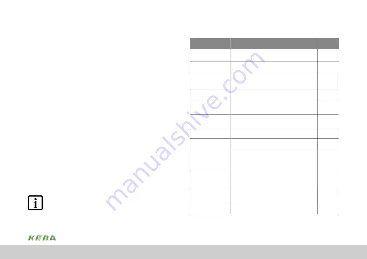
1.3  Reference documents

Document

Contents

ID no. 

Format

ServoOne junior - 

Operation Manual

Safety, mechanical installation, electrical installation, commissioning, 

diagnostics, specifications, certification and applicable standards, 

technical data

1300.20B.x 

PDF

ServoOne Single-Axis 

System - 

Operation Manual

Safety, mechanical installation, electrical installation, 

commissioning, diagnostics, specifications, certification and 

applicable standards, technical data

1100.20B.x 

PDF

ServoOne Multi-Axis System - 

Operation Manual

Safety, mechanical installation, electrical installation, commissioning, 

diagnostics, STO, operation with servocontroller as supply, planning, 

application example, specifications, certification and 

applicable standards, technical data

1101.20B.x 

PDF

ServoOne Multi-Axis System 

Supply Unit - 

Operation Manual

Safety, mechanical installation, electrical installation, commissioning, 

diagnostics, specification, certification and applicable standards,  

technical data

1101.21B.x 

PDF

ServoOne Sercos II - 

User Manual

Safety, commissioning, communication phases, parameter interface, 

error, warning and status messages, operation modes, weighting, 

referencing, touchprobe, parameter lists

1100.29B.x 

PDF

ServoOne Sercos III - 

User Manual

Safety, installation and connection, commissioning and configuration, 

setting parameters, data transmission, scaling and weighting, 

functionality, error message and diagnostics, parameter lists

1108.26B.x 

PDF

CANopen/EtherCAT - 

User Manual

Safety, commissioning, data transmission, operation modes, 

referencing, parameters, technical data

1108.28B.x

PROFIBUS-DPV

User Manual

Description and configuration of the parameters for the ServoOne 

on the PROFIBUS-DPV field bus system

1108.27B.x

PDF

ServoOne System -  

System Catalogue

Information, notes on ordering, specifications and 

technical data on:

ServoOne junior, ServoOne single-axis system, ServoOne multi-axis 

system, safety technology, communication, technology, function 

packages, accessories and motors

1100.24B.x

PDF

ServoOne - device help

Description of the software functionality ServoOne,  

firmware versions: 

- SO junior from V1.30-xx

- SO single-axis system from V3.25-xx

- SO multi-axis system from V3.25-xx

0842.26B.x 

PDF and HTML

Program help DriveManager 5 

PC user software 

Context-sensitive help for DriveManager version 5.x graphic PC 

user software for initial commissioning and serial commissioning, 

operation, diagnostics and project management

0842.25B.x 

PDF and HTML

UL-Certification

Notes on UL-compliant mounting and usage

0927.21B.x 

PDF

Summary of Contents for ServoOne Series

Page 1: ...ServoOne Multi Axis System Operation Manual Supply Unit Multi axis system with sinusoidal regeneration ...

Page 2: ...multi axis machine controller or with distributed programmable Motion Control intelligence in the drive controller the ServoOne is a master of both Subject to technical change without notice The content of our documentation was compiled with the greatest care and attention and based on the latest information available to us We should nevertheless point out that this document cannot always be updat...

Page 3: ...sions 26 3 8 Mounting mains filter 27 3 8 1 Dimensions 27 4 Electrical installation 29 4 1 Before you start 29 4 2 Effective EMC installation 30 4 2 1 Cable type 30 4 2 2 Routing of cables 30 4 2 3 Earthing measures 30 4 2 4 Shielding measures 31 Table of contents 1 General 7 1 1 Target group 7 1 2 Prerequisites 7 1 3 Reference documents 7 1 4 Order code 8 1 5 Data on manufacture 8 1 6 Scope of su...

Page 4: ... 2 8 Setting DC link voltage 64 5 2 9 Setting monitoring of the braking resistor 64 4 3 Overview of the connections 32 4 3 1 Layout BG5 SO84 040 S and SO84 076 S 32 4 3 2 Layout BG6a SO84 115 S and SO84 170 S 32 4 3 3 Overview of connections BG5 and BG6a 33 4 3 4 Connection diagram BG5 34 4 3 5 Connection diagram BG6a 35 4 3 6 Layout BG7 SO84 375 S and SO84 540 S 36 4 3 7 Overview of connections B...

Page 5: ...bus address menu Fb 69 6 Diagnostics 71 6 1 Device states 71 6 1 1 Errors 71 6 2 Error list 72 A Appendix 75 A 1 Technical data supply unit 75 A 2 Current required for the control supply 79 A 3 Pre assembled connection cables 79 A 4 Hydrological data for the liquid cooling 80 A 5 Dynamic temperature monitoring 80 A 6 Ambient conditions 81 A 7 Technical data step up choke 82 A 8 Technical data inpu...

Page 6: ...Operation Manual ServoOne Supply Unit 6 ID no 1101 21B 6 00 Date 04 2020 Table of contents ...

Page 7: ... diagnostics specifications certification and applicable standards technical data 1100 20B x PDF ServoOne Multi Axis System Operation Manual Safety mechanical installation electrical installation commissioning diagnostics STO operation with servocontroller as supply planning application example specifications certification and applicable standards technical data 1101 20B x PDF ServoOne Multi Axis ...

Page 8: ...ion package Basic without additional function package iPlc 1 Special design None 0 Protection PCBs with protective varnish 1 Hardware version May be multi digit X 1 in preparation 1 5 Data on manufacture On the rating plate for the SOVE you will find the serial number from which you can identify the date of manufacture based on the following key For the location of the rating plate on the SOVE ref...

Page 9: ...ual signify the following for the user NOTE Useful information or reference to other documents 1 digit ACTION TO BE TAKEN Action undertaken by the user or the system You will find the pictograms used in this operation manual for safety instructions and warnings in chapter 2 Safety 1 8 Disclaimer Following the documentation on the devices from KEBA is a prerequisite y y For safe operation y y To ac...

Page 10: ...Operation Manual ServoOne Supply Unit 10 ID no 1101 21B 6 00 Date 04 2020 ...

Page 11: ... charge So check that electrical power is not present See also the warning label on the front panel on the device Rotating parts Automatically starting drives Hot components and surfaces 3 Protection against magnetic and or electromagnetic fields during installation and operation Persons fitted with heart pacemakers metallic implants and hearing aids etc must not be allowed access to the following...

Page 12: ...in this document and on the device DANGER Risk of injury due to rotating parts on the motor Carelessness will result in serious injuries or death Follow safety instructions and warnings in this document Pay attention to special safety instructions and warnings that are given here in the document before a specific action and that warn the user about a specific hazard Note The pictograms may also be...

Page 13: ...rvoOne multi axis system The ServoOne supply unit is intended for use in a ServoOne multi axis system The multi axis system comprises at least one ServoOne CMP supply unit with the mains connection set and several ServoOne DC axis controllers connected to it In motor operation the supply unit draws energy from the supply system and makes it available to the DC axis controllers connected via the DC...

Page 14: ... specific application for the devices other laws standards and directives with provisions on Safety may apply If necessary contact the machine or system manufacturer Note Due to possible output frequencies 600 Hz the drive controllers fall under Dual Use Regulation EU no 1382 2014 dated 22 October 2014 item 3A225 Export authorisation is therefore required for non EU countries Please note the infor...

Page 15: ...pply unit in a ServoOne multi axis system it is also imperative the operation manual for the DC axis controllers is followed 3 1 1 Arrangement and mounting The following guidelines apply in principle to the supply unit and DC axis controller y y The backing plate must be well earthed y y To attain the best result for effective EMC installation you should use a chromated or galvanised backing plate...

Page 16: ...y y Divide the switch cabinet into zones with different power and interference levels y y For devices susceptible to interference maintain a distance of at least 200 mm from the following components Drive controller Input and output chokes transformers Mains motor DC power supply and braking resistor cables even if shielded Relay and contactors even if interference suppressed y y For small distanc...

Page 17: ... must be bare metal to establish a good ground connection to the switch cabinet ground There must not be an air gap between the rear wall of the drive controller and the wall of the switch cabinet y y The bases of the chokes must have good contact to the switch cabinet ground The contact area must be bare metal to establish a good ground connection to the switch cabinet ground 0 mm 1 2 0 mm 1 2 1 ...

Page 18: ... all ServoOne DC axis controllers in a line along the top edge of the devices see line A in Figure 3 4 This action is necessary to be able to make the DC link connections Align the supply unit BG6a and all ServoOne DC axis controllers in a line along the top edge of the devices see line A in Figure 3 5 This action is necessary to be able to make the DC link connections Move down the mounting bores...

Page 19: ...C1 6 10 H1 418 5 600 H2 15 20 H3 64 166 D 5 6 10 Fastening screws 4 x M5 4 x M8 E Direct butt mounting max 2 mm Direct butt mounting max 2 mm 40 2 F 3 180 G 3 300 500 All dimensions in mm 1 Without terminals connectors 2 Mounting distance BG6a to other BG6a 3 Also pay attention to the bending radius of the connection cables Table 3 1 Dimensions wall mounting housing variant Note On butt mounting d...

Page 20: ...ntroller BG6a and the supply unit BG6 by approx 20 mm see red line B in Figure 3 9 This action is necessary to be able to make the DC link connections Align all ServoOne DC axis controllers and the supply unit BG7 in a line along the top edge of the devices see line A in Figure 3 10 Move down the mounting bores for the supply unit BG7 by approx 28 mm and for the DC axis controller BG6a by approx 2...

Page 21: ...oOne DC BG1 ServoOne DC BG2 ServoOne DC BG3 ServoOne DC BG4 ServoOne DC BG5 ServoOne DC BG6a with liquid cooling ServoOne Supply unit BG7 with liquid cooling B A 20 mm 28 mm 40 mm Figure 3 10 Butt mounting axis group with liquid cooling and supply unit BG7 Mechanical installation ...

Page 22: ... 540 Sxxx 8 Weight kg 13 32 90 B width 190 280 380 H height 1 345 540 855 T depth 1 238 285 287 A 150 200 150 A1 40 65 29 A2 70 C 406 5 581 955 C1 6 10 14 H1 418 5 600 979 9954 H2 15 20 62 H3 54 57 124 H4 64 166 T1 74 D 6 5 10 12 Mounting screws 4 x M6 4 x M8 6 x M10 S Female thread 3 8 inch female thread D1 48 bore for pipe fitting E 2 Direct butt mounting Butt mounting 9 mm 40 mm distance see Fi...

Page 23: ...g e g viewed from the left BG4 BG3 BG2 BG1 This arrangement will minimise the thermal interaction The supply unit must always be fitted beside the axis controller with the highest power E G F F Figure 3 13 Mounting distance liquid cooling housing variant BG5 BG6a symb depiction G F F E Figure 3 14 Mounting distance liquid cooling housing variant based on BG7 as an example Mechanical installation ...

Page 24: ...97 127 All dimensions in mm and not including terminals connectors Table 3 3 Dimensions step up choke Note The step up choke is only intended for installation in a switch cabinet because the filter is designed in degree of protection IP00 without protection against touching 3 5 Cooling circuit connection Note Connect the flow from the liquid cooling to the connection marked The cooling circuit mus...

Page 25: ...he switch cabinet on robust mounting rails that permit unhindered air flow from below On selecting the position the area of the air inlet at the filter mat or even better at the fan blowing in air is to be recommended Note It is imperative you wire the temperature sensor integrated into the winding on the step up choke to terminal X5 for temperature monitoring A1 A H T D1 B Figure 3 16 Dimensional...

Page 26: ...rea will provide good contact The contact area must be bare metal to establish a good ground connection to the switch cabinet ground 3 7 1 Dimensions For size BG5 BG6a BG7 For device SO84 040 SO84 076 SO84 115 SO84 170 SO84 375 SO84 540 B width 289 289 342 348 297 357 H height 252 268 292 321 347 565 T depth 119 136 175 175 319 308 A 156 156 176 176 224 310 A1 63 80 95 95 145 146 D1 7 x 13 7 x 13 ...

Page 27: ...170 SO84 375 SO84 540 Type FFU 3 x 56 K FFU 3 x 80 K FFU 3 x 130 K FFU 3 x 180 K FN 3359 400 99 FN 3359 600 99 B width 85 80 90 130 260 260 H height 250 270 270 380 300 300 T depth 90 135 150 180 115 135 A 60 60 65 102 235 235 C 235 225 255 365 120 120 G Ø 5 4 6 5 6 5 6 5 12 12 Mounting screws M5 M6 M6 M6 M10 M10 Weight kg 1 9 2 6 4 2 6 0 10 5 11 All dimensions in mm and not including terminals co...

Page 28: ...upply of the axis controllers is an effective remedy here For detailed information on the use of common mode filters see Chapter 4 2 5 or refer to the Mounting instruction Common Mode Filter CMR ID no 1101 13B x H B T A C Ø G PE Figure 3 20 Dimensional drawing mains filter for BG5 and BG6a Fig differs from the original H B A T C C Ø G PE Figure 3 21 Dimensional drawing mains filter for BG7 Fig dif...

Page 29: ...n relation to earth to ensure they are not carrying any electrical power If necessary all cable connections are to be discharged using suitable means Warning Risk of injury due to electrical power Carelessness may result in serious injuries or death A dangerous voltage may be present at the device even if the device does not emit any visual or audible signals indications e g for BG5 and BG6a with ...

Page 30: ... not be necessary to remove the paint The ServoOne supply unit has a galvanised sheet steel back panel y y For further information on the cross section of the protective earth conductor see 4 5 Connection of the protective earth conductor 4 2 Effective EMC installation 4 2 1 Cable type y y Use only shielded mains motor and signal cables as shown in Figure 4 7 p 35 For all shielded connections use ...

Page 31: ...must have good contact to the switch cabinet ground The contact area must be bare metal to establish a good ground connection to the switch cabinet ground 4 2 4 Shielding measures You should take into account the following points for the shielding measures y y Use only shielded mains motor and signal cables as shown in Figure 4 7 p 35 For all shielded connections use cables with double copper brai...

Page 32: ...n The common mode choke should be used if a There are more than 3 4 DC axis controllers in the network or b the motor cable lengths per axis controller are greater than 10 m or in total of all axes be more than 30 m Note Typical servo cables have approx 0 47 nF m corresponds to a permissible total leakage capacitance of approx 15 nF Note that values of 1 nF m or more can easily be achieved with ca...

Page 33: ...4 3 Overview of the connections In the following you can see the layout where you can find the corresponding positions of the connectors and terminals For improved clarity we have added an abbreviation to the designation for the connectors and terminals 4 3 1 Layout BG5 SO84 040 S and SO84 076 S PE X21 X11 X9 X10 Option 1 D1 D2 T1 T2 X2 X3 X4 X5 SW HW X12 Figure 4 4 Layout BG5 Electrical installat...

Page 34: ...odule for field bus e g SERCOS PROFIBUS DP EtherCAT or CANopen p 54 X2 USB 1 1 interface Service interface Plug Play connection to PC p 54 X3 Ethernet interface Service interface fast TCP IP connection RJ45 p 54 X4 Control connections 8 digital inputs 3 digital outputs 1 additional relay output p 51 X5 Connection for tempera ture monitoring KTY temperature sensor for step up choke X10 X9 Connectio...

Page 35: ...cables 10 Circuit breaker 11 Multi axis system on off 12 External 24 V DC control supply 13 Auxiliary contactor precharging synchronisation 14 Connection DC link precharging and mains synchroni sation 15 Floating contact active once precharging completed 250 VAC 5 A or 30 VDC 6 A Caution Is not allowed to be connected to SELV or PELV circuits 16 ServoOne supply unit BG5 17 AC mains connection 18 B...

Page 36: ...cuit breaker 11 Multi axis system on off 12 External 24 V DC control supply 13 Auxiliary contactor precharging synchronisation 14 Connection DC link precharging and mains synchronisation 15 Floating contact active once precharging completed 250 VAC 5 A or 30 VDC 6 A Caution Is not allowed to be connected to SELV or PELV circuits 16 ServoOne supply unit BG6a 17 AC mains connection 18 Braking resist...

Page 37: ...1 24V UH 3 4 5 6 10 15 16 17 9 23 24 22 RSH 12 11 1 2 14 13 PE L1 L2 L3 ISD03 ISD04 ISD05 18 19 20 ISD06 21 OSD01 8 OSD00 7 OSD04 DGND DGND X12 X4 X2 D1 D2 T 1 T 2 Ethernet X3 X11 DC link Top Bottom Front Option 1 Communication Fieldbusses KTY temp sensor for set up reactor X5 RB RB Braking resitor Mains supply ZK ZK ZK PE PE ZK Reserve 1 2 3 4 5 6 7 X44 Relay for operating the pre charging 24 V D...

Page 38: ...emperature sensor for step up choke X6 Option No function X7 Option No function X8 Option No function X11 DC power supply Connection for DC link PE connection p 48 X12 Power connection braking resistor PE connection precharging mains synchronisation p 54 p 40 p 45 X44 Connection for control supply relay 24 V supply for control electronics relay for operating the precharging terminals 5 to 7 not co...

Page 39: ... depiction of the connection diagram The position of the terminals may vary depending on the device Incorrect wiring can cause irreparable damage to the supply unit Note You will find a selection of possible mains contactors circuit breakers and fuses in chap A 11 p 85 The switching over of the DC link precharging to the mains is realised externally on BG7 devices The connection diagram in Figure ...

Page 40: ...axis controllers For this purpose use the pre assembled protective earth conductors 3 Please take into account the local and national regulations and conditions The minimum cross section of the protective earth conductor must comply with the local safety requirements for protective earth conductors for equipment with high leakage current 4 4 Mains On Off control process Precharging the DC link Swi...

Page 41: ...1 PE on the butt mounted DC axis controllers Connect the PE connection X11 PE on the first DC axis controller in a row to the PE rail main earth in the switch cabinet For this purpose use the pre assembled protective earth conductors ServoOne DC BG 1 ServoOne DC BG 2 ServoOne DC BG 3 ServoOne DC BG 4 ServoOne DC BG 5 ServoOne Supply unit BG 6a X12 PE PE X11 PE X11 PE X11 PE X11 PE X11 PE X11 Figur...

Page 42: ...lly live Before making any change the device is to be disconnected from the mains Dangerously high voltages 50 V can be present on the DC link connections and other components in the mains input area after power off So check that electrical power is not present See chap 4 1 Figure 4 15 Detail connection of the protective earth conductor 4 5 3 Protective earth conductor X11 supply unit BG7 1 Earth ...

Page 43: ... The control electronics with their logic µP the inputs and outputs are electrically isolated from the power section power supply DC link All control connections are designed as safety extra low voltage protective extra low voltage SELV PELV circuits and are only allowed to be operated with 5 V to 50 V as per the relevant specification This provides reliable protection against electric shock on th...

Page 44: ...nnection for control supply Note By means of suitable measures provide adequate cable protection e g fuse 10 A gG If the permissible current carrying capacity is exceeded an additional separate control supply must be connected Note Along with the control section the external control supply also supplies the digital inputs and outputs ICONTROL SECTION II O Also pay attention to the current 24V DC G...

Page 45: ... minor injuries or damage For safety reasons the connection X21 HREL on BG5 and BG6a is not allowed to be connect ed to SELV PELV circuits drawn by all axis controllers on starting and in operation See chap A 2 p 79 Note Do not use the connector as a switch for a reset Specification control supply Control supply X9 1 2 UV 24 V DC 20 10 stabilised and smoothed For max starting continuous current se...

Page 46: ...or connection diagrams for BG5 BG6a and BG7 see from chap 4 3 3 and following text 4 7 4 Precharging X44 and mains synchronisation X45 for BG7 The regenerative unit is synchronised with the mains via the terminals X45 S1 S2 S3 SN The regenerative unit in the BG7 is pre charged via the terminals X45 P1 P2 P3 This contact is disconnected again from the main after pre charging by means of an auxiliar...

Page 47: ...00 kVA 1 Rsc is defined as the short circuit ratio of the short circuit power Sk at the mains connection to the rated power Sn of the ServoOne supply unit Rsc Sk Sn Table 4 9 Mains connection conditions Procedure 1 Define the cable cross section according to local regulations and conditions Use shielded cables where necessary and as shown in the connection diagrams 2 Wire the supply unit to the ma...

Page 48: ...Operation without a cover is not allowed 4 8 1 Connection DC power supply X11 BG5 1 Connect terminal X11 on the supply unit to terminal X11 on the next DC axis controller in the row Connect the DC power supply cable on the DC axis controller to the next DC axis controller in the row For this purpose use the pre assembled DC power supply cables 2 Connect terminal X11 on the supply unit to terminal ...

Page 49: ...eve for the shielding The length of 2 m should not be exceeded Define the cable cross section to suit the application however use as a minimum 50 mm2 CU Pay attention to the local situation and conditions During the dimensioning of the DC connection cables please take into account that the DC currents can be up to 1 4 times the mains side input current Given corresponding design cable protection f...

Page 50: ...21 2 2 1 DC fuses required 2 For the connection of further axis controllers BG5 and smaller see Figure 4 22 Figure 4 24 Schematic connection DC power supply BG7 to BG6a BG7 ServoOne DC BG 6a X11 ServoOne Versorgungs einheit BG 6a X11 X12 L3 L2 L1 PE RB ZK 2 1 3 1 Shortest connection 2 Alternatively the DC link connection on terminal X12 can be used 3 For the connection of further axis controllers ...

Page 51: ...t circuit proof Imax 50 mA PLC compatible Terminal scan cycle in 1 ms High side driver Yes Table 4 10 Specification of the control connections 4 9 Control connections X4 1 Check whether a complete device setup is already available i e whether the drive has already been configured 2 If so a special control terminal assignment applies It is imperative you contact your project engineer to obtain the ...

Page 52: ...02 OSD01 OSD00 ISA1 ISA1 ISA0 ISA0 24V DGND 24 23 22 21 20 19 18 17 16 15 14 13 12 11 10 9 8 7 6 5 4 3 2 1 X4 REL X4 23 X4 24 Relay 1 NO contact Functions can be selected as for digital outputs 25 V 1 0 A AC cos ϕ 1 30 V 1 0 A DC cos ϕ 1 Switching delay approx 10 ms Cycle time 1 ms X4 23 X4 24 Yes RSH RSH X4 11 X4 12 No function Yes Auxiliary voltage 24 V X4 2 X4 14 Auxiliary voltage for supplying...

Page 53: ...WLPOW Active power limit exceeded defined in P 0730 16 17 29 OUTPUT_FS_GRID_OK Mains OK frequency AND voltage within the tolerance window HIGH Table 4 12 Functions that can be selected for the digital outputs OSD00 to OSD02 4 10 Functions of the digital inputs The following functions can be selected for the digital inputs ISD00 to ISD06 Value Value name Description 0 MPRO_INPUT_FS_OFF No function ...

Page 54: ...t be disconnected from the mains All drive controllers in the system must also be deactivated WARNING Risk of injury due to hot surfaces on the braking resistor Carelessness may result in serious burns The braking resistor may become hot during operation For this reason maintain an adequate clearance to neighbouring assemblies or install the braking resistor outside the switch cabinet 4 12 Specifi...

Page 55: ...le A 3 Table A 6 and Table A 9 y y The cables are to be protection by suitable means 4 16 Overview of the step up choke connections In the following you will find the layout with the corresponding positions and labels on the terminals The temperature is evaluated using a KTY sensor via terminal X5 At 145 C the supply unit is shut down For technical data on the step up choke see chap A 7 p 82 DANGE...

Page 56: ...ata on the input choke see chap A 8 p 83 DANGER Risk of injury due to electrical power Carelessness will result in serious injuries or death The choke is only intended for installation in a switch cabinet as with IP00 protection it offers no protection against direct or indirect touching BG5 76 A BG5 40 A Figure 4 28 Connections input choke for BG5 and BG6a L1 PE L1 L2 L2 L3 L3 Figure 4 27 Step up...

Page 57: ...ervoOne Supply Unit 57 ID no 1101 21B 6 00 Date 04 2020 L1 L2 L3 PE L1 L2 L3 Figure 4 29 Connections input choke for BG7 BG6a 115 A BG6a 170 A Figure 4 28 Connections input choke for BG5 and BG6a Electrical installation ...

Page 58: ...find the layout with the corresponding positions and labels on the terminals For technical data on the mains filter see chap A 9 p 84 L1 1 L2 1 L3 1 L1 L2 L3 PE PE L1 L2 L3 PE L1 1 L2 1 L3 1 PE Figure 4 30 Connections mains filter for BG5 and BG6a PE L3 L2 L1 PE L3 L2 L1 Figure 4 31 Mains filter based on BG7 as an example Electrical installation ...

Page 59: ...to electrical power Carelessness will result in serious injuries or death Never make or disconnect electrical connections while they are electrically live Before making any change the device is to be disconnected from the mains Dangerously high voltages 50 V can be present on the DC link connections and other components in the mains input area after power off So check that electrical power is not ...

Page 60: ...nection Terminals Terminal identifier Cable type 24 V DC X4 22 ISDSH Standard shielded ENPO Start X4 10 ENPO Standard shielded See chap 4 9 p 51 Table 5 3 Communication via terminals 5 2 1 System requirements y y Supply unit installed You will find details on initial commissioning in chap 5 2 2 p 60 y y Completion of the work in chap 4 Electrical installation and chap 3 Starting DriveManager 5 in ...

Page 61: ...onnel The parameter changes described in the following adapt the supply unit to the parameters of the supply system and to the number and type of the DC axis controllers connected to the DC terminals X11 Note The firmware in the supply unit must be compatible with DriveManager 5 If the establishment of the communication fails the compatibility must be checked 5 2 3 Switching on control voltage 24 ...

Page 62: ...cking the Save button using the mouse Figure 5 3 Saving setting 1 2 5 2 5 Setting mains voltage and mains frequency of the supply system 4 The supply unit parameters are configured in the factory for a system with 3 x 400 V AC 50 Hz If the supply unit is to be operated on such a system you can continue with step 5 If the supply unit is to be operated on a different system the parameters P 0307 mai...

Page 63: ...itance and the equivalent time constant for the current regulation 5 The DC voltage regulator in the supply unit regulates the DC link voltage to an internally specified fixed setpoint The regulation is dependent on the DC link capacitance in the multi axis system and the equivalent time constant for the current regulation Both values can and should be determined using the automatic identification...

Page 64: ...ers are also effective after a restart the modified settings must be saved in the device in non volatile memory and a 24 V reset undertaken All the necessary parameter configuration work has then been completed 5 2 8 Setting DC link voltage 7 The supply unit regulates the DC link voltage to an internally specified fixed setpoint At an input voltage of 400 VAC the DC link voltages 650 and 770 VDC a...

Page 65: ... Any pre heating of the braking resistor is not taken into account 5 2 10 Switching on mains supply voltage NOTE Prior to switching on check the wiring for correct phase angle 9 The mains can now be switched on using the main switch Once the precharging of the DC link has been completed the indication on the display in the supply unit changes from the value 1 to the value 2 5 2 11 Switching on reg...

Page 66: ...play is immediately switched to the indication of the error code y y Parameter setting indication PA see chap 5 4 3 p 68 Resetting device parameters to their factory setting y y Ethernet IP address setting indication IP see chap 5 4 4 p 68 Ethernet IP address and subnet mask setting y y Field bus settings indication Fb see chap 5 4 5 p 69 E g field bus address setting 5 4 Integrated control unit T...

Page 67: ...ctivate the different menus and to control the corresponding functions Button Function Comment T1 left Activate the menu exit the device status display Scroll through the menus sub menus Set values left segment display D1 The button T1 can be held pressed for any length of time because the display will only scroll through the menu commands available at the corresponding level No settings will be c...

Page 68: ...net mask in hexadecimal format e g FF in 255 255 255 0 b3 00 FF Subnet mask update byte 3 Setting for byte 3 of the subnet mask in hexadecimal format e g FF in 255 255 255 0 Sr Subnet mask reset to factory setting Reset subnet mask to factory setting 255 255 255 0 Table 5 9 IP address menu 5 4 3 Parameter menu PA The following functions are available on the Parameter menu y y Reset device to facto...

Page 69: ...address Setting for field bus address only if field bus option used otherwise indication The maximum value that can be programmed depends on the option Po 0 3 or Transmit power Setting for fibre optic power output only with SERCOS II option otherwise display Table 5 10 Field bus address menu Example configuration of the subnet mask In this example the subnet mask is changed from 255 255 255 0 to 1...

Page 70: ...x Tx back back T2 T2 T1 T2 T1 T2 T1 T2 back accept 5 s 5 s 5 s 5 s T1 T2 T1 T2 T1 T2 Value NOT saved Value saved T1 T2 T1 several actuations of buttonTx X 1 2 until the desired menu appears in the display single actuation of button Tx X 1 2 simultaneous actuation of both buttons T1 and T2 Actuation of any button Figure 5 9 Example configuration of the field bus address Commissioning ...

Page 71: ...6 2 p 72 Fault 1 This not a safe indication in the context of EN 61800 5 2 Table 6 1 Device states Note The safety function STO Safe Torque OFF is not required for the ServoOne supply unit as no motors are connected To be able to start the supply unit a jumper must be placed between X4 14 and X4 22 If this jumper is forgotten there is a flashing point on the device display The safety function STO ...

Page 72: ...CAN option 00 Unknown CAN option error 01 CAN option BusOff error 02 CAN option Guarding error Table 6 3 Error list 6 2 Error list Error messages error number error location error text for the supply unit are listed in the following table In there is an error the display on the supply unit changes cyclically between the indications Er Error number Error location The error messages can be acknowled...

Page 73: ...erved 20 PLC error Table 6 3 Error list Error number Error location Error text 03 CAN option Message transmit failed 04 CAN option Heartbeat error 05 CAN option Illegal address 06 CAN option mapping error 07 CAN option Sync RxPDO timeout error 13 Error in SERCOS option 00 Unknown SERCOS error 01 SERCOS option Error while hardware initialisation 02 SERCOS option Illegal communication phase 03 SERCO...

Page 74: ...ion Unknown error 01 PROFIBUS option process data timeout 22 Task overload 00 Internal timing error 01 Internal timing error 02 Internal timing error 23 Power fail detected 00 Power fail detected 24 Error braking chopper 00 Unknown braking chopper error 01 P t integrator value exceeds maximum Table 6 3 Error list You will find further information on error management in the ServoOne device help Dia...

Page 75: ...BG5 Device SO84 040 Sxxx x SO84 076 Sxxx x Brake chopper power electronics 1 Response threshold 2 VDC 820 Peak braking power kW software hardware side 90 99 Minimum ohmic resistance of an exter nally installed braking resistor 7 5 Ω Continuous chopper power kW 2 1 Optional for liquid cooling internal braking resistor mounted on the base of the cooler on request 2 Minimum switch on time 250 µs Tabl...

Page 76: ...20 000 μF Size BG6a Device SO84 115 Sxxx x SO84 170 Sxxx x Mains input voltage 10 V AC 400 460 480 400 460 480 Regulated DC link voltage V DC 650 770 770 650 770 770 Input mains side Continuous current AAC eff 115 115 96 170 170 142 Peak current 1 AAC 195 195 163 245 245 204 Switching frequency kHz 8 4 Continuous power kW 80 118 Power dissipation 2 W 2500 Asymmetry of the mains voltage 3 max Frequ...

Page 77: ... Device SO84 115 SO84 170 X11 L L Cable cross section Use the pre assembled connection cables supplied or 35 95 mm2 AWG 2 AWG 3 0 1 Tightening torque 25 30 Nm 221 265 lb in X11 PE Screw size for ring cable lug M8 Tightening torque 10 12 Nm 88 106 lb in X12 L1 L2 L3 Cable cross section 50 150 mm2 10 95 mm2 2 AWG 0 AWG 5 0 1 50 150 mm2 AWG 0 AWG 5 0 1 Tightening torque 25 30 Nm 221 265 lb in X12 PE ...

Page 78: ...tion depends on the cross section of the phase conductor see chap 4 5 p 40 The minimum cross section of the connection cables depends on the local regulations conditions as well as on the rated current of the supply unit Table A 9 Terminals BG7 Size BG7 Device SO84 375 S SO84 540 S Brake chopper power electronics 1 Response threshold 2 VDC 820 Peak braking power kW software hardware side 210 Minim...

Page 79: ...ble laying and the ambient temperature Type L Cross section Model Connection DC link BG5 193 mm 20 mm Flat copper braid covered with double heatshrink sleeve Flat lug with hole Ø 5 5 mm on both ends Sketch L 4 15 Table A 11 Technical data pre assembled connection cables A 2 Current required for the control supply Size BG5 BG6a BG7 Device SO84 040 SO84 076 SO84 115 SO84 170 SO84 375 SO84 540 Termin...

Page 80: ... device due to condensation on the cooling plate Carelessness can cause condensation on the cooling plate and as a consequence irreparable damage to the device The temperature of the cooling plate is not allowed to be more than 10 C below the ambi ent temperature Note Adequate heating of the water chiller is to be provided by the customer Requirements Limits Coolant quality Recommended tap water c...

Page 81: ...ity is limited to max 60 g m This means at 70 C for example that the relative atmospheric humidity may only be max 40 2 The absolute humidity is limited to max 29 g m So the maximum values for temperature and relative atmospheric humidity stipulated in the table must not occur simultaneously 3 The absolute humidity is limited to max 25 g m That means that the maximum values for temperature and rel...

Page 82: ...lb in KTY sensor Cable cross section flexible with ferrule 0 5 2 5 mm2 AWG 30 AWG 12 Tightening torque 0 4 0 8 Nm 3 5 7 0 lb in Table A 18 Technical data step up choke Mechanical conditions ServoOne Vibration limit in transit As per EN 61800 2 IEC 60721 3 2 class 2M1 Frequency Hz Amplitude mm Acceleration m s 2 f 9 3 5 Not applicable 9 f 200 Not applicable 10 200 f 500 Not applicable 15 Shock limi...

Page 83: ...tening torque 1 5 2 4 Nm 13 2 21 2 lb in 4 5 Nm 35 4 44 2 lb in 4 5 Nm 35 4 44 2 lb in 12 20 Nm 106 2 177 lb in Table A 20 Technical data input choke For size BG7 For device SO84 375 S SO84 540 S Rated AC current 3 x 375 A 3 x 540 A Supply voltage 3 x 400 VAC 3 x 480 VAC 3 x 400 VAC 3 x 480 VAC Designed for active power step up operation 650 VDC 770 VDC 250 kW 360 kW Power dissipation at 100 duty ...

Page 84: ...ly voltage 3 x 400 VAC 3 x 480 VAC Connection Busbar Protection IP 00 Power connections L1 L2 L3 Connection lug for ring cable lug Ø 10 5 mm Tightening torque The screw size and tightening torque depend on the ring cable lug used Protective earth conductor connections PE 1 Rated AC current at 40 C ambient temperature Table A 23 Technical data mains filter for BG7 For size BG7 For device SO84 375 S...

Page 85: ...36 Siemens 3RT1076 6AB36 Coil voltage 24 VDC 24 VDC Rated current AC 3 up to 500 V 400 A 500 A Table A 27 Technical data mains contactor for BG7 For size BG7 For device SO84 375 S SO84 540 S Thread M12 Tightening torque The screw size and tightening torque depend on the ring cable lug used 1 Rated AC current at 40 C ambient temperature Table A 23 Technical data mains filter for BG7 A 10 Technical ...

Page 86: ... For device SO84 040 SO84 076 SO84 115 SO84 170 Type Siemens 3RV1721 1ED10 Siemens 3RV1721 1GD10 Rated current up to AC 500 V 10 4 A 6 3 A Table A 28 Technical data circuit breaker For size BG7 For device SO84 375 S SO84 540 S Type Siemens 3RV1721 1GD10 Rated current up to AC 500 V 10 6 3 A Table A 29 Technical data circuit breakers for system protection A 13 UL certification The description of al...

Page 87: ...4 50 Control supply BG5 and BG6a 43 BG7 44 Control unit 66 Buttons T1 and T2 67 Display 67 Cooling Liquid cooling 80 Cooling circuit 24 D Date of manufacture 8 DC power supply 47 Connection BG5 47 Connection BG6a 48 Connection BG7 49 Declaration of conformity 14 Device states 71 Dimensional drawings Input choke with film capacitor 26 Mains filter 27 Step up choke 24 Dimensions 22 Disclaimer 9 Disp...

Page 88: ...59 Pollution degree 81 Pre assembled connection cables 79 Precharging BG5 and 6a 44 BG7 38 Protective earth conductor 39 Other components 41 Supply unit BG5 39 Supply unit BG6a 40 Supply unit BG7 41 F Firmware 61 H Hydrological data for the liquid cooling 80 I IEC 60721 3 81 Initial commissioning 59 Input choke Connections 55 Dimensions 26 Technical data 83 Inputs digital 52 Installation start 29 ...

Page 89: ...bles 30 S Safety instructions and warnings 12 Saving setting 62 Scope of supply 8 Serial number 8 Service Helpline 9 ServoOne multi axis system 13 Shielding measures 31 Step up choke Connections 54 Dimensions 24 Technical data 82 Switch cabinet layout 16 T Technical data BG5 75 BG6a 76 BG7 77 Circuit breaker 85 Input choke 83 Mains contactor 85 Mains filter 84 Mains fuse 84 Step up choke 82 U UL c...

Page 90: ...Operation Manual ServoOne Supply Unit 90 ID no 1101 21B 6 00 Date Date 04 2020 Glossary ...

Page 91: ...Operation Manual ServoOne Supply Unit 91 ID no 1101 21B 6 00 Date 04 2020 ...

Page 92: ...49 6441 966 0 fax 49 6441 966 137 info keba de KEBA AG Headquarters Gewerbepark Urfahr 4041 Linz Austria telephone 43 732 7090 0 fax 43 732 730910 keba keba com KEBA Group worldwide China Germany India Italy Japan Netherlands Austria Romania Switzerland South Korea Taiwan Czech Republic Turkey USA Copyright 2020 KEBA All rights reserved All content of the documentation in particular the text photo...

Reviews: