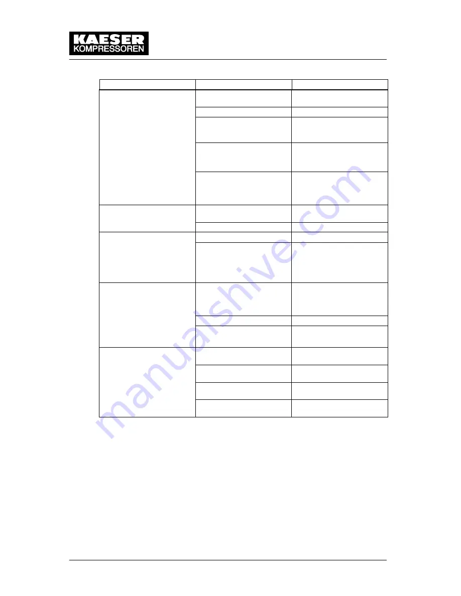
Event Recognition and Fault Rectification
9 --- 51
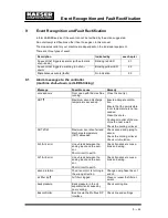
Fault
Remedy
Possible cause
Machine runs but produces
no compressed air.
Inlet valve not opening or
only opening partially.
no compressed air.
Venting valve not closing.
Leaks in the pressure sys-
tem.
Check pipework and con-
nections for leaks and
tighten any loose fittings.
Air consumption is greater
than the capacity of the
compressor.
Check compressed air net-
work for leaks.
Shut down the consumer(s).
Hose coupling or mainten-
ance hose still plugged into
the quick ---release coupling
on the oil separator tank.
Remove coupling or main-
tenance hose.
Cooling oil runs out of the
air filter.
Oil level in the oil separator
tank too high.
Drain off oil until the correct
level is reached.
air filter.
Inlet valve defective.
Compressor switches be-
tween load and idle (off
Air receiver too small.
Compressor switches be-
tween load and idle (off
load) more than twice per
minute.
Flow into the compressed
air network restricted.
Increase air pipe diameters.
Check filter elements.
Switching difference too
small (e.g. p1 SD)
Cooling oil leaking into the
floor pan.
Hose coupling or mainten-
ance hose still plugged into
the quick ---release coupling
on the oil separator tank.
Remove coupling or main-
tenance hose.
Oil cooler leaking
Connections leaking.
Tighten connection fittings.
Replace seals.
Cooling oil consumption too
high.
Unsuitable oil is being used.
Use SIGMA FLUID cooling
oil.
high.
Oil separator cartridge split.
Change the oil separator
cartridge.
Oil level in the oil separator
tank too high.
Drain off oil until the correct
level is reached.
Oil return line clogged.
Check dirt trap in the oil re-
turn line.
Tab. 40
Other faults and actions
Summary of Contents for CSD 102
Page 2: ......
Page 85: ......
Page 86: ......
Page 87: ......
Page 88: ......
Page 89: ......
Page 90: ......
Page 95: ......
Page 96: ......
Page 97: ......
Page 98: ......
Page 99: ......
Page 100: ...Appendix 13 92 13 1 2 Pipeline and instrument flow diagram option C1...
Page 101: ......
Page 102: ......
Page 103: ......
Page 104: ......
Page 105: ......
Page 106: ...Appendix 13 98 13 1 3 Dimensional drawing 13 1 3 1 Air cooling option K1...
Page 107: ......
Page 108: ......
Page 109: ...Appendix 13 101 13 1 3 2 Water cooling option K2...
Page 110: ......
Page 111: ......
Page 112: ...Appendix 13 104 13 1 4 Electrical diagram...
Page 113: ......
Page 114: ......
Page 115: ......
Page 116: ......
Page 117: ......
Page 118: ......
Page 119: ......
Page 120: ......
Page 121: ......
Page 122: ......
Page 123: ......
Page 124: ......
Page 125: ......
Page 126: ......
Page 127: ......
Page 128: ......
Page 129: ......
Page 130: ......
Page 131: ......
Page 132: ......
Page 133: ......
Page 134: ......

