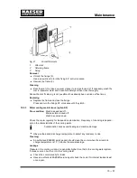

Maintenance
10 --- 71
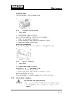
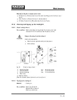
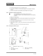
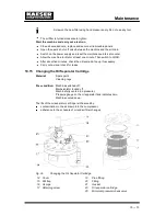
Remove the protective screen (1, Fig. 33) and turn the coupling (2, Fig. 33) by hand at
least five revolutions until all the oil has run out.
Replace and secure the safety screen (1, Fig. 33).
Close the shut ---off valve (3) and unplug the hose.
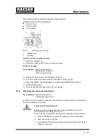
Turning the coupling can cause a small amount of oil to flow back to the cooler and separ-
ator tank.
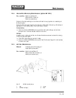
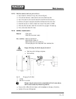
Drain oil from the separator tank via the hose coupling (9, Fig. 30).
Drain oil from the oil cooler via the hose coupling (2, Fig. 31).
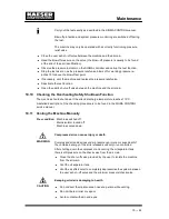
10.13.4 Draining the oil from the heat recovery system (option W1/W2/W3)
Pre --- condition: Machine fully vented (no pressure)
Pressure gauge on the oil separator tank indicates zero.
The procedure is dependent on the heat recovery system installed.
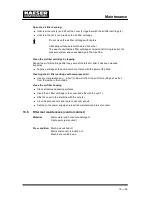
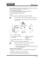
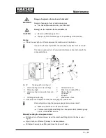
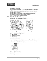
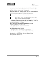
Internal heat recovery (option W2 / W3)
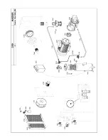
Fig. 34
Cooling oil changing, internal heat recovery
1
Hose coupling
2
Thermostatic valve
3
Shut ---off valve
Have an oil container ready.
With the shut ---off valve closed, insert the male hose fitting (6 in Fig. 31) into the hose
coupling (1) on the thermostatic valve (2).
Place the end of the maintenance hose in the oil container and secure it in place.
Open the shut ---off valve (3) and (7, Fig. 31) and wait for the cooling oil to drain out.
Close the shut ---off valve (3) and unplug the hose.
Prepared for heat recovery (option W1)
Have an oil container ready.
Use the maintenance hose to drain the oil from the drain point of the heat recovery
system.
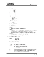
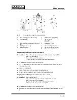
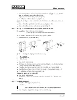
10.13.5 Filling with cooling oil
Open the oil filler plug (4, Fig. 30) slowly.
Fill with oil.
Machines with heat recovery systems need correspondingly more oil.
Check the plug and gasket for damage and re---insert the plug.
Summary of Contents for CSD 102
Page 2: ......
Page 85: ......
Page 86: ......
Page 87: ......
Page 88: ......
Page 89: ......
Page 90: ......
Page 95: ......
Page 96: ......
Page 97: ......
Page 98: ......
Page 99: ......
Page 100: ...Appendix 13 92 13 1 2 Pipeline and instrument flow diagram option C1...
Page 101: ......
Page 102: ......
Page 103: ......
Page 104: ......
Page 105: ......
Page 106: ...Appendix 13 98 13 1 3 Dimensional drawing 13 1 3 1 Air cooling option K1...
Page 107: ......
Page 108: ......
Page 109: ...Appendix 13 101 13 1 3 2 Water cooling option K2...
Page 110: ......
Page 111: ......
Page 112: ...Appendix 13 104 13 1 4 Electrical diagram...
Page 113: ......
Page 114: ......
Page 115: ......
Page 116: ......
Page 117: ......
Page 118: ......
Page 119: ......
Page 120: ......
Page 121: ......
Page 122: ......
Page 123: ......
Page 124: ......
Page 125: ......
Page 126: ......
Page 127: ......
Page 128: ......
Page 129: ......
Page 130: ......
Page 131: ......
Page 132: ......
Page 133: ......
Page 134: ......


