background image

Safety and Responsibility

3 --- 14

3.4

Safety Devices

Do not change, bypass or disable safety devices.

Do not remove or obliterate labels and notices.

Ensure that labels and notices are clearly legible.

More information on safety devices is contained in chapter 4 ’Design and Function’, sec-
tion 4.4 ’Safety Devices’.

3.5

Dangers

The general safety instructions in this chapter indicate the possible dangers and how to
deal with them.

Special safety instructions are found in this service manual at the beginning of each
chapter or directly before handling instructions.

3.5.1

Awareness of danger sources

Here are to be found the various types of danger that can arise in connection with machine
operation.

Electricity

Allow only qualified electricians or trained personnel under the supervision of a quali-
fied electrician to work on electrical equipment according to electrical engineering re-
gulations.

Before initial start ---up, make sure that adequate protection against electric shock from
direct or indirect contact with the machine is installed and checked.

Isolate all phases of the main power supply.

Check that there is no voltage present.

Switch off any external power sources.
These can be, for example, power supplied through a volt ---free (dry) contact or electri-
cal machine heating.

Use fuses corresponding to the machine power.

Regularly check that all electrical connections are tight.

Pressure forces

Compressed air is a contained force. Uncontrolled release of this energy can cause seri-
ous injury or death.

Before all work on a pressure system:

close shut ---off valves or otherwise isolate the machine from the air network to ensure
that no compressed air can flow back into the machine,

de---pressurize all pressurized components and enclosures.

Do not carry out welding, heat treatment or mechanical modifications to pressure com-
ponents (e.g. pipes and vessels) as this influences the component’s pressure resis-
tance.
The safety of the machine is then no longer ensured.

Compressed air quality

Use appropriate systems for air treatment before using the compressed air from this
machine as breathing air and/or for the processing of foodstuffs.

Never directly inhale compressed air.

Use foodstuff---compatible cooling oil whenever compressed air is to come into con-
tact with foodstuffs.

Summary of Contents for CSD 102

Page 1: ...SERVICE MANUAL Screw Compressor Model CSD No 9_5700_06E Manufacturer KAESER KOMPRESSOREN GmbH 96410 Coburg PO Box 2143 GERMANY Tel 49 0 9561 6400 Fax 49 0 9561 640130 http www kaeser com...

Page 2: ......

Page 3: ...2 7 2 9 2 Power supply specifications 2 7 2 10 Water cooling option K2 2 9 2 10 1 Design data 2 9 2 10 2 Cooling Water Quality 2 9 2 11 Heat Recovery 2 10 2 11 1 Prepared for heat recovery option W1...

Page 4: ...allation Conditions 5 28 5 2 1 Place of installation and space required 5 28 5 2 2 Ventilation 5 29 5 2 3 Operating in a compressed air network 5 30 6 Installation 6 31 6 1 Safety 6 31 6 2 Reporting T...

Page 5: ...4 10 2 4 Regular service work 10 55 10 3 Cooler Maintenance 10 56 10 3 1 Air cooling option K1 10 56 10 3 2 Filter mat maintenance option K3 10 56 10 3 3 Water cooling maintenance option K2 10 57 10 4...

Page 6: ...ddresses 11 76 11 5 Spare Parts for Service and Repair 11 76 12 Decommissioning Storage and Transport 12 83 12 1 De commissioning 12 83 12 2 Packing 12 83 12 3 Storage 12 84 12 4 Transporting 12 84 12...

Page 7: ...rgency 8 41 Fig 19 Acknowledging and resetting warning and alarm messages 8 42 Fig 20 Cleaning the cooler 10 56 Fig 21 Cooler filter mats 10 57 Fig 22 Air filter maintenance 10 58 Fig 23 Ventilator gr...

Page 8: ...a 10 K 2 9 Tab 22 Water cooling design data 30 K 2 9 Tab 23 Cooler specification water cooling 2 9 Tab 24 Cooling Water Quality 2 10 Tab 25 Heat capacity option W1 2 10 Tab 26 Water Quality Specificat...

Page 9: ...ake sure you give the data from the nameplate 1 3 Copyright This service manual is copyright protected Please contact KAESER if you have any queries regarding the use and duplication of this documenta...

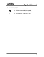
Page 10: ...this Document 1 2 1 4 2 Other notices and symbols This symbol indicates a task to be carried out This symbol identifies environmental protection measures This symbol indicates particularly important i...

Page 11: ...ature Tab 1 Nameplate A summary of the included options helps to relate the service manual information to your machine Please enter details of options Option Code Exists Air cooling K1 Water cooling K...

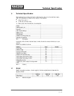
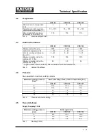
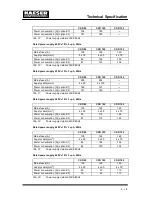
Page 12: ...r hu midity at 31 C 100 100 100 Maximum relative inlet air hu midity at 45 C 50 50 50 Higher elevation permissible only after consultation with the manufacturer Tab 5 Ambient Conditions 2 4 Pressure S...

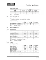
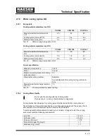
Page 13: ...72 Tab 9 Sound Pressure Level 2 7 Motor and Performance 2 7 1 Compressor motor CSD 82 CSD 102 CSD 122 Rated power kW 45 55 75 Rated speed rpm 50 Hz 2965 2965 2978 Rated speed rpm 60 Hz 3568 3568 3580...

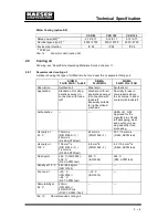
Page 14: ...d oil for all applications except in connection with foodstuff Especially suitable for lightly utilized machines Specially for use in compressors where the air comes in direct contact with foodstuff A...

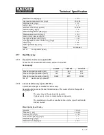
Page 15: ...Connection to an IT supply is not permitted without further measures insulation monitor ing Further requirements Further requirement for the three phase supply apply to machines with frequency control...

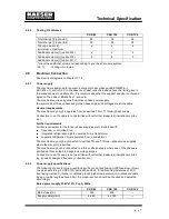
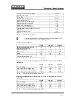
Page 16: ...on K2 151 185 Tab 17 Power supply details 230V 3 60Hz Rated power supply 380V 10 3 ph 60Hz CSD 82 CSD 102 CSD 122 Mains fuses A 125 125 160 Supply cable mm2 4 x 50 4 x 50 4 x 70 Power consumption A op...

Page 17: ...oling water end bar 10 UNsuitable cooling medium Seawater Consult Kaeser before using cooling water solu tions Max permissible discharge tempera ture C 70 Tab 23 Cooler specification water cooling 2 1...

Page 18: ...t capacity CSD 82 CSD 102 CSD 122 Max heat capacity available kW 40 3 49 4 58 1 Max heat capacity available MJ h 145 178 209 Max heat capacity available kcal h 34669 42511 49940 Tab 25 Heat capacity o...

Page 19: ...e drop bar 0 1 0 1 0 1 Plate material 1 4401 1 4401 1 4401 Solder Cu Cu Cu Maximum permissible temperature of the heat transfer medium C 100 100 100 Tab 27 General specification of the heat exchanger...

Page 20: ...includes compliance with the instructions in this manual Operate the machine only within its performance limits and under the permitted ambi ent conditions 3 2 Unspecified Use Never direct compressed...

Page 21: ...dangers of electrical and compressed air de vices and take appropriate measures to safeguard persons and property in the case of machines with refrigeration dryers must be able to recognise the poss i...

Page 22: ...d and checked Isolate all phases of the main power supply Check that there is no voltage present Switch off any external power sources These can be for example power supplied through a volt free dry c...

Page 23: ...chine heaters Wear protective clothing When welding is taking place on or near the machine take adequate measures to en sure that no parts of the machine or any oil vapours can ignite because of spark...

Page 24: ...Only use pressure lines that are suitable and approved for the maximum working pres sure and medium used Do not allow connecting pipes to be under mechanical stress Do not step onto machine component...

Page 25: ...in accord ance with local environmental regulations Give refrigerant only to authorised bodies for disposal Dispose of the machine in accordance with local environmental regulations 3 5 3 Organising...

Page 26: ...be switched on again locked off Check that no voltage is present 2 Hot surface Danger of burns from touching hot components Do not touch the surface Wear long sleeved garments not synthetics such as...

Page 27: ...g 7 Wrong cooling oil level Machine damage or excessive oil remaining the compressed air Check the oil level regularly and top up as necessary Tab 32 Safety signs Fig 1 Location of safety signs 3 8 In...

Page 28: ...ing oil to escape to the environment or into the sewage system Store and dispose of operating materials and replaced parts in accordance with local envi ronment protection regulations Observe national...

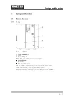
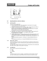
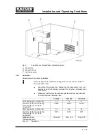
Page 29: ...atch 3 Removable panel The cabinet when closed serves various purposes Sound damping Protection Cooling air flow control Safe and reliable operation can only be ensured with the cabinet closed Latches...

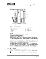
Page 30: ...heat in the oil cooler 9 The oil then flows through the filter 4 and back to the point of injec tion Pressure within the machine keeps the oil circulating A separate pump is not necess ary A thermost...

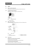
Page 31: ...ter mat 4 2 3 Water cooling option K2 Plate heat exchangers in stainless steel are used for water cooled machines Fig 5 Water cooling 1 Oil cooler 3 Cooling water connection 2 Compressed air aftercool...

Page 32: ...AD option C1 The proportional controller continuously varies the degree of opening of the inlet valve and thereby the delivery rate of the compressor in re sponse and in proportion to the air demand T...

Page 33: ...ing time and the idle standstill time The shorter these time settings the sooner and more frequently the motor is stopped 4 3 4 Modulating control option C1 The modulating control mode is an extension...

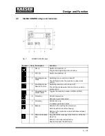
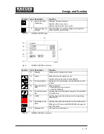
Page 34: ...ching remote control on and off The LED illuminates when the machine is under re mote control 5 Operating mode LOAD IDLE Toggles the machine between LOAD and IDLE 6 Arrow key Scrolls down menu Reduces...

Page 35: ...Alarm Blinks red when an alarm occurs Lights continuously when acknowledged 14 Communication Lights red if communication via the Profibus is inter rupted 15 Service warning LED Blinks yellow for main...

Page 36: ...ambient conditions ambient temperature and humidity clean inlet air with no damaging contaminants inlet air free of explosive or chemically unstable gases or vapours inlet air free of acid forming su...

Page 37: ...essor room is at least equivalent to that being removed from it by the compressor and exhaust fan Make sure that the machine and exhaust fan can only operate when the inlet aperture is actually open C...

Page 38: ...machine is connected to an air network the network operating pressure must not exceed 16 bar Initial filling of a fully vented air network generally creates very a high rate of flow through air treat...

Page 39: ...sure check valves pressure relief valves and inlet valves are powerfully spring loaded Fatal injury may occur from incorrect opening of spring loaded compo nents Do not open or dismantle valves Instal...

Page 40: ...30 and 523 in Germany for example Check the reaction time of overload protection devices e g DIN VDE 0100 part 413 Guide values are given in chapter 2 9 The user must provide the machine with a lockab...

Page 41: ...holes are contained in the dimensional drawing in chapter 13 1 3 Use appropriate bolts to anchor the machine 6 5 2 Water cooling connection option K2 The dimensional drawing in chapter 13 1 3 gives th...

Page 42: ...ler technical specification Connect the cooling water line to the fitting Open the shut off valve on the cooling water outlet A Slowly open the cooling water inlet shut off valve B to gradually fill t...

Page 43: ...ve pressure Blowoff pressure and capacity are related to the user s installation design Keep to the heat exchanger technical specification Connect the water lines to the fittings Open the shut off val...

Page 44: ...eld pressure gauge to ensure that all read zero Initial start up may only be carried out by authorised personnel Before switching on ensure that no one is working on the machine all panels are in plac...

Page 45: ...or option H1 6 5 1 14 Are all access doors closed and latched and all removable panels in place and secured 4 1 1 Tab 37 Installation conditions checklist 7 4 Setting the overload protection cut out C...

Page 46: ...otational direction arrow 4 Grasp the coupling 2 and turn it and the airend shaft 1 Replace the coupling cover 3 7 7 Checking Direction of Rotation The machine is designed for a clockwise field Check...

Page 47: ...ate and delivers compressed air Watch for any faults occurring in the first hour of operation After the first 50 operating hours carry out the following Check that all electrical connections are tight...

Page 48: ...8 1 1 Switching on Ensure that no one is working on the machine all panels are in place all access doors are closed no parts of the machine are colder than 3 C Switch on the supply isolating device Af...

Page 49: ...hing Off in an Emergency and Switching On Again Fig 18 Switching off in an emergency 9 EMERGENCYSTOP button Switching off Press the EMERGENCY STOP button 9 The EMERGENCY STOP button remains latched in...

Page 50: ...control device has control of the machine The machine can still be switched on and off by the ON and OFF keys 2 and 3 if re quired 8 4 Switching On and Off with the Clock Pre condition The clock is pr...

Page 51: ...hes for example if a maintenance task is due The display shows the latest acquired value Warning coming LED flashes Warning acknowledged LED illuminates Warning reset LED out or Warning coming LED fla...

Page 52: ...ge temperature exceeded Ensure adequate ventila tion Ensure that the permissible room temperature is not ex ceeded Clean the cooler Cooling air outlet of the ma chine too near a wall Check the cooling...

Page 53: ...omer specific No data ext message 5 fan M2 I Shutdown of 1st fan motor because of overload Investigate cause of shut down Reset overload trip fan M3 I Shutdown of 2nd fan motor because of overload Inv...

Page 54: ...erature too low Contact KAESER service PD temperature Package discharge tem perature too high Check the fan motor Clean the cooler Check the cooling oil level pRV The activating pressure of the pressu...

Page 55: ...e belts Tab 38 Alarm messages and actions 9 2 Warning messages on the controller yellow LED flashes Message Possible cause Remedy access doors Doors opened with the ma chine shut down Close access doo...

Page 56: ...erval counter error RS 485 Wrong configuration or transmission error Check the link interface connections between the two controllers Check maximum cable length and screening 1 master and 1 slave conf...

Page 57: ...Check for air leaks Check the value for internal pressure given in the ana log data menu with the re ading on the oil separator tank pressure gauge oil filter dp Oil filter clogged Oil filter replacem...

Page 58: ...the sys press low value Air consumption too high Check air demand Check transducer connec tions and wiring Check sys press low set ting system press vacuum machines only System pressure is above the s...

Page 59: ...ter Inlet valve defective Compressor switches be tween load and idle off Air receiver too small Compressor switches be tween load and idle off load more than twice per minute Flow into the compressed...

Page 60: ...ves are powerfully spring loaded Fatal injury may occur from incorrect opening of spring loaded compo nents Do not open or dismantle valves Call for authorised service if a fault occurs Uncontrolled p...

Page 61: ...onal devices Necessary mainten ance tasks are signalled by the SIGMA controller Keep a log of all service work This enables the frequency of individual maintenance tasks to be compared with KAESER s r...

Page 62: ...every 3 years Change the oil separator cartridge 10 15 Every 2000 h but at least annually Grease the motor bearings 10 7 Every 3000 hours Check the coupling 10 8 variable see table 42 Change the cool...

Page 63: ...als 10 2 4 Regular service work Only authorised KAESER service agents should carry out service work When operating conditions are unfavourable e g dusty atmosphere or when the equipment is heavily uti...

Page 64: ...machine damage Avoid dust disturbance Wear breathing apparatus if necessary Do not use sharp objects to clean the cooler The cooler could be damaged A severely contaminated cooler should be cleaned by...

Page 65: ...ion K2 Pre condition Machine switched off Mains isolator locked off Machine cooled down Check the cooler regularly for leaks and contamination Frequency of checking is depend ant on the characteristic...

Page 66: ...R service agent clean the heat exchanger as soon as a pressure drop in the heat transfer medium is detected Leakage If a leak occurs cooling oil can flow into the heat transfer medium as pressure the...

Page 67: ...mes Tap the cartridge at the end a number of times with the palm of the hand Cleaning the air filter cartridge with compressed air Use dry compressed air 5 bar to blow dirt from the air filter cartrid...

Page 68: ...cleaning is not possible or has already been carried out five times Replacing Lay the filter mat in the frame and push on the grill to latch 10 7 Electric Motor Maintenance Material Bearing grease Cle...

Page 69: ...is equipped with grease nipples for re greasing the bearings Fig 25 Fan motor maintenance 1 Grease nipple Clean the grease nipple 1 with a rag See chapter 2 7 2 for the required grease volume Grease b...

Page 70: ...pling changed by an authorised KAESER Service agent Refit the safety screen Close all access doors and replace all cover panels 10 9 Checking the pressure relief valve Pre condition Machine switched o...

Page 71: ...utdown Function The machine should shut down if the airend discharge temperature reaches 110 C A detailed description of the checking procedure is to be found in the SIGMA CONTROL service manual 10 11...

Page 72: ...ance hose lie beneath the oil separator tank Fig 27 Ventilate the machine 1 Hose coupling air cooler venting 6 Male hose coupling fitting 2 Pressure gauge 7 Shut off valve A closed B open 3 Hose coupl...

Page 73: ...t five minutes under load minimum 50 Hz for machines under frequency control Danger of burning from hot surfaces Skin burns are possible Wear long arm garments and protective gloves Work carefully Fig...

Page 74: ...g oil 1 Hose coupling air cooler venting 5 Oil level indicator 2 Pressure gauge 6 Male hose coupling fitting 3 Hose coupling oil separator tank ven ting 7 Shut off valve A closed B open 4 Oil filling...

Page 75: ...it to idle for at least one minute Then switch to LOAD After about five minutes check the oil level and top up if necessary Carry out a visual check for leaks 10 13 Changing the Cooling Oil Material C...

Page 76: ...ure gauge on the oil separator tank indicates zero Close the shut off valve 10 in the venting line Start the machine in idle mode and watch the oil separator tank pressure gauge 2 until it reads 3 5 b...

Page 77: ...suit operating conditions Have an oil container ready With the shut off valve closed insert the male hose fitting 6 in Fig 30 into the hose coupling 9 Fig 30 Place the end of the maintenance hose in t...

Page 78: ...e shut off valve 3 and unplug the hose 10 13 3 Draining the oil from the airend Pre condition Machine fully vented no pressure Pressure gauge on the oil separator tank indicates zero Fig 32 Changing t...

Page 79: ...system installed Internal heat recovery option W2 W3 Fig 34 Cooling oil changing internal heat recovery 1 Hose coupling 2 Thermostatic valve 3 Shut off valve Have an oil container ready With the shut...

Page 80: ...Carry out a visual check for leaks 10 14 Oil filter maintenance Material Spare parts Have the oil container ready Pre condition Machine switched off Mains isolator locked off Machine fully vented no...

Page 81: ...the oil level and top up if necessary Carry out a visual check for leaks 10 15 Changing the Oil Separator Cartridge Material Spare parts Cleaning rags Pre condition Machine switched off Mains isolator...

Page 82: ...ld oil separator element 23 together with the gaskets 21 and dispose of according to environmental regulations Wipe all sealing faces with a cleaning rag Insert the new oil separator cartridge with ga...

Page 83: ...Maintenance 10 75 10 16 Logging Maintenance Work Machine number Date Maintenance task carried out Operating hours Signature Tab 44 Maintenance log...

Page 84: ...to the original These are correct for use in our machines Machine Name Quantity Number Air filter cartridge 1 1250 Filter mat control cabinet ventilator 2 1100 Filter mat cooler 1 1050 Oil filter 1 12...

Page 85: ......

Page 86: ......

Page 87: ......

Page 88: ......

Page 89: ......

Page 90: ......

Page 91: ...load for at least 30 minutes Machine switched off and fully vented The supply disconnecting device is switched off and locked out The machine is cooled down completely In water cooled machines discon...

Page 92: ...gaskets 12 4 Transporting 12 4 1 Safety Transport only by fork truck or lifting cradle and with personnel trained in the safe use of the transport equipment The water cooling system of water cooled ma...

Page 93: ...upports flanges attached components such as centrifugal separators condensate drains or filters rain protection covers The diagram shows how the machine should be lifted by a cradle Fig 38 Transport w...

Page 94: ...Annex 13 86 13 Annex 13 1 Diagrams and Drawings 13 1 1 Pipeline and instrument flow diagram P I diagrams...

Page 95: ......

Page 96: ......

Page 97: ......

Page 98: ......

Page 99: ......

Page 100: ...Appendix 13 92 13 1 2 Pipeline and instrument flow diagram option C1...

Page 101: ......

Page 102: ......

Page 103: ......

Page 104: ......

Page 105: ......

Page 106: ...Appendix 13 98 13 1 3 Dimensional drawing 13 1 3 1 Air cooling option K1...

Page 107: ......

Page 108: ......

Page 109: ...Appendix 13 101 13 1 3 2 Water cooling option K2...

Page 110: ......

Page 111: ......

Page 112: ...Appendix 13 104 13 1 4 Electrical diagram...

Page 113: ......

Page 114: ......

Page 115: ......

Page 116: ......

Page 117: ......

Page 118: ......

Page 119: ......

Page 120: ......

Page 121: ......

Page 122: ......

Page 123: ......

Page 124: ......

Page 125: ......

Page 126: ......

Page 127: ......

Page 128: ......

Page 129: ......

Page 130: ......

Page 131: ......

Page 132: ......

Page 133: ......

Page 134: ......

Reviews: