Event Recognition and Fault Rectification
9 --- 47
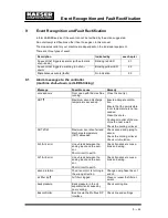
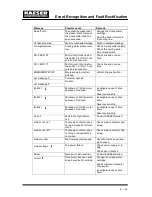
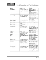
Message
Remedy
Possible cause
SIGMA CONTROL T
Maximum permissible
temperature in SIGMA
CONTROL housing ex-
ceeded.
Ensure adequate ventila-
tion.
Ensure that the permissible
room temperature is not ex-
ceeded.
Check control cabinet venti-
lator (filter mats).
sh.cct.AI 1/AI 2
The connection between
the sensor and the analog
input is shorted.
Check transducer connec-
tions and wiring.
sh.cct.AI 5/AI 6
The connection between
the sensor and the analog
input is shorted.
Check transducer connec-
tions and wiring.
soft start
Fault in the soft start equip-
ment.
Contact KAESER service.
Start
Airend discharge tempera-
ture (ADT) too low. Ambient
temperature below + 3˚ C.
Heat the compressor room.
V---belts broken
The V---belts parted during
operation.
Replace the belts.
Tab. 38
Alarm messages and actions
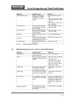
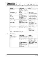
9.2
Warning messages on the controller (yellow LED flashes)
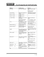
Message
Possible cause
Remedy
access doors
Doors opened with the ma-
chine shut down.
Close access doors.
ADT
Maximum airend discharge
temperature will soon be re-
ached.
Ensure sufficient ventilation
Clean the cooler.
The machine’s cooling air
outlet is too near a wall.
Check the cooling oil level.
Replace the oil filter.
air filter dp
The pressure drop across
the air filter is too high.
Air filter element clogged.
Clean/replace the air filter
element.
air filter h
The interval for the air filter
element check has expired.
Clean/replace the air filter
element.
annual maint.
The maintenance interval
counter was not reset within
a year.
Carry out necessary main-
tenance and reset one of the
following maintenance inter-
val counters: oil filter, oil
separator, oil change or air
filter.
bearing maint. h
The maintenance interval
for greasing the bearings
has expired.
Grease the motor bearings.
Summary of Contents for CSD 102
Page 2: ......
Page 85: ......
Page 86: ......
Page 87: ......
Page 88: ......
Page 89: ......
Page 90: ......
Page 95: ......
Page 96: ......
Page 97: ......
Page 98: ......
Page 99: ......
Page 100: ...Appendix 13 92 13 1 2 Pipeline and instrument flow diagram option C1...
Page 101: ......
Page 102: ......
Page 103: ......
Page 104: ......
Page 105: ......
Page 106: ...Appendix 13 98 13 1 3 Dimensional drawing 13 1 3 1 Air cooling option K1...
Page 107: ......
Page 108: ......
Page 109: ...Appendix 13 101 13 1 3 2 Water cooling option K2...
Page 110: ......
Page 111: ......
Page 112: ...Appendix 13 104 13 1 4 Electrical diagram...
Page 113: ......
Page 114: ......
Page 115: ......
Page 116: ......
Page 117: ......
Page 118: ......
Page 119: ......
Page 120: ......
Page 121: ......
Page 122: ......
Page 123: ......
Page 124: ......
Page 125: ......
Page 126: ......
Page 127: ......
Page 128: ......
Page 129: ......
Page 130: ......
Page 131: ......
Page 132: ......
Page 133: ......
Page 134: ......

