Maintenance
10 --- 54
10.2.2
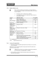
Regular maintenance work
When operating conditions are unfavourable (e.g. dusty atmosphere) or
when the equipment is in frequent use, maintenance tasks must be carried
out more frequently.
Pay attention to the controller’s service messages.
Have KAESER Service adjust the maintenance interval counters to
suit operating conditions.
Interval
Maintenance tasks
see chapter
weekly
Check cooling oil level.
10.12.1
weekly
Clean or renew the filter mats.
10.3.2 / 10.6
Every 1000 hours
Oil and air cooler maintenance.
10.3
Every 1000 hours
Heat recovery system maintenance.
10.4
Indicated by
SIGMA CONTROL
Air filter maintenance.
10.5
Indicated by
SIGMA CONTROL
but at least an-
nually.
Change the oil filter.
10.14
Indicated by
SIGMA CONTROL
but at least every
3 years.
Change the oil separator cartridge.
10.15
Every 2000 h, but at
least annually.
Grease the motor bearings.
10.7
Every 3000 hours
Check the coupling.
10.8
variable (see
table) 42
Change the cooling oil.
10.13
annually
Check that all electrical connections are tight.
annually
Check the pressure relief valve.
10.9
Check the overheating safety shutdown function
10.10
Check the oil and air coolers for leaks.
10.3
h. = operating hours
Tab. 41
Regular maintenance work
10.2.3
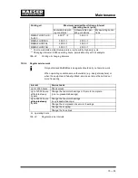
Cooling oil changing intervals
Please observe national regulations regarding the use of cooling oil in oil ---injected
screw compressors.
Machine duty cycle and ambient conditions are important criteria for the number and
length of the change intervals.
KAESER Service will support you in determining appropriate intervals and
provide information on the possibilities of oil analysis.
Check operating conditions and adjust intervals as necessary; keep results in a
table 42for future reference.
Summary of Contents for CSD 102
Page 2: ......
Page 85: ......
Page 86: ......
Page 87: ......
Page 88: ......
Page 89: ......
Page 90: ......
Page 95: ......
Page 96: ......
Page 97: ......
Page 98: ......
Page 99: ......
Page 100: ...Appendix 13 92 13 1 2 Pipeline and instrument flow diagram option C1...
Page 101: ......
Page 102: ......
Page 103: ......
Page 104: ......
Page 105: ......
Page 106: ...Appendix 13 98 13 1 3 Dimensional drawing 13 1 3 1 Air cooling option K1...
Page 107: ......
Page 108: ......
Page 109: ...Appendix 13 101 13 1 3 2 Water cooling option K2...
Page 110: ......
Page 111: ......
Page 112: ...Appendix 13 104 13 1 4 Electrical diagram...
Page 113: ......
Page 114: ......
Page 115: ......
Page 116: ......
Page 117: ......
Page 118: ......
Page 119: ......
Page 120: ......
Page 121: ......
Page 122: ......
Page 123: ......
Page 124: ......
Page 125: ......
Page 126: ......
Page 127: ......
Page 128: ......
Page 129: ......
Page 130: ......
Page 131: ......
Page 132: ......
Page 133: ......
Page 134: ......

