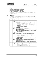

Installation
6 --- 32
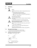
Shut ---off valve (2) to be installed by the user in the connection line.
Make the compressed air connection with a flexible hose (1) or an axial compensa-
tor (1).
6.4
Electrical Connection
Have the electrical connection made only by a qualified and authorised electrician.
Carry out protection measures as stipulated in relevant regulations (IEC 364 or DIN
VDE 0100, for example) and in national accident prevention regulations (BGV A2 in Ger-
many). Also observe the regulations of the local power utility company.
Use wire conductor dimensions and fuse ratings in accordance with local regulations (DIN
VDE 0100 parts 430 and 523 in Germany, for example).
Check the reaction time of overload protection devices (e.g. DIN VDE 0100 part 413).
Guide values are given in chapter 2.9.
The user must provide the machine with a lockable mains---disconnecting device.
This could be, for example, a switch ---disconnector with fuses. If a circuit breaker is
used it must be suitable for the motor starting characteristics.
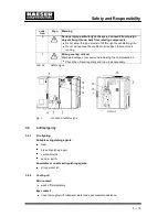
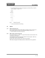
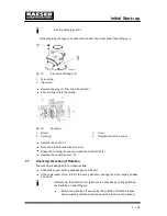
Before Initial Start--- up
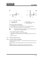
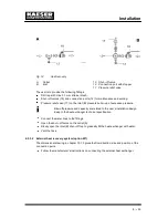
The control transformer in the control cabinet has connections for various supply volt-
ages. Check that the correct connections are made for the supply voltage provided for
the machine. If necessary, re---connect the transformer to match the supply voltage
using the
5% taps. (see Fig. 11 and chapter 13.1.4)
1
1
1
1
2
2
3
3
4
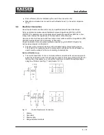
Fig. 11
Control Transformer Connection
1
Primary
2
Secondary
3
Mains supply
4
Bridge between terminals
Summary of Contents for CSD 102
Page 2: ......
Page 85: ......
Page 86: ......
Page 87: ......
Page 88: ......
Page 89: ......
Page 90: ......
Page 95: ......
Page 96: ......
Page 97: ......
Page 98: ......
Page 99: ......
Page 100: ...Appendix 13 92 13 1 2 Pipeline and instrument flow diagram option C1...
Page 101: ......
Page 102: ......
Page 103: ......
Page 104: ......
Page 105: ......
Page 106: ...Appendix 13 98 13 1 3 Dimensional drawing 13 1 3 1 Air cooling option K1...
Page 107: ......
Page 108: ......
Page 109: ...Appendix 13 101 13 1 3 2 Water cooling option K2...
Page 110: ......
Page 111: ......
Page 112: ...Appendix 13 104 13 1 4 Electrical diagram...
Page 113: ......
Page 114: ......
Page 115: ......
Page 116: ......
Page 117: ......
Page 118: ......
Page 119: ......
Page 120: ......
Page 121: ......
Page 122: ......
Page 123: ......
Page 124: ......
Page 125: ......
Page 126: ......
Page 127: ......
Page 128: ......
Page 129: ......
Page 130: ......
Page 131: ......
Page 132: ......
Page 133: ......
Page 134: ......


