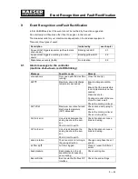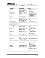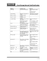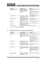
Initial Start--- up
7 --- 38
Use the same type of oil.
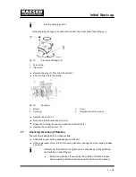
A sticker giving the type of oil used is found near the oil separator tank filling port.
Fig. 15
Inlet valve oil filling port
1
Screw plug
2
Inlet valve
Remove the plug (1) from the inlet valve (2).
Pour cooling oil into the airend.
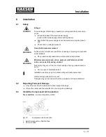
Fig. 16
Coupling
1
Airend
3
Cover
2
Coupling
4
Rotational direction arrow
Remove the cover (3).
Note the rotational direction arrow (4).
Grasp the coupling (2) and turn it and the airend shaft (1).
Replace the coupling cover (3).
7.7
Checking Direction of Rotation
The machine is designed for a clockwise field.
Check the supply with a phase sequence indicator.
If the compressor motor turns in the wrong direction, change the motor supply phases
L1 and L2.
Alternatively, the direction of rotation can be checked by briefly switching
the machine on and off again.
Switch the machine off as soon as the direction of rotation is seen
and compare it with the direction arrows on the motor and airend.
Summary of Contents for CSD 102
Page 2: ......
Page 85: ......
Page 86: ......
Page 87: ......
Page 88: ......
Page 89: ......
Page 90: ......
Page 95: ......
Page 96: ......
Page 97: ......
Page 98: ......
Page 99: ......
Page 100: ...Appendix 13 92 13 1 2 Pipeline and instrument flow diagram option C1...
Page 101: ......
Page 102: ......
Page 103: ......
Page 104: ......
Page 105: ......
Page 106: ...Appendix 13 98 13 1 3 Dimensional drawing 13 1 3 1 Air cooling option K1...
Page 107: ......
Page 108: ......
Page 109: ...Appendix 13 101 13 1 3 2 Water cooling option K2...
Page 110: ......
Page 111: ......
Page 112: ...Appendix 13 104 13 1 4 Electrical diagram...
Page 113: ......
Page 114: ......
Page 115: ......
Page 116: ......
Page 117: ......
Page 118: ......
Page 119: ......
Page 120: ......
Page 121: ......
Page 122: ......
Page 123: ......
Page 124: ......
Page 125: ......
Page 126: ......
Page 127: ......
Page 128: ......
Page 129: ......
Page 130: ......
Page 131: ......
Page 132: ......
Page 133: ......
Page 134: ......

