122
JVL Industri Elektronik A/S - User Manual - Ethernet for MAC and MIS motors
5.3.2
Mechanical installation
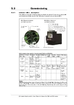
The network cables must be connected to the two M12 connectors (marked “L/A IN”
and “L/A OUT”) at the MAC module and “CN2” and “CN3” at the MIS/MIL motors.
The cable from the MN is connected to either of the two ports. In the line topology, if
there are more slave devices in the same line, the next slave device is connected to the
second port. If there is a redundant ring, the second port of the last slave device is con-
nected to the second port of the MN.
See also the illustration in the chapter
Standard CAT 5 FTP or STP cables can be used. It is not recommended to use UTP ca-
bles in industrial environments, which is typically very noisy.
5.3.3
Quick start
This section describes the steps to configure the PLC, B&R X20 CP1485, with B&R Au-
tomation Studio PC software, so that it can be used to control the drive.
Set node ID
1. Connect the RS232 communication cable.
2. Apply power to the motor, and make sure the PWR LED is lit.
3. Open MacTalk and select the “MAC00-EL (Powerlink)” tab.
4. Change the last number in the IP address (= node ID), to one that doesn't conflict
with other devices on the sub net.
5. Press “Apply and save”.
Installation
6. Connect an Ethernet RJ45-M12 cable to IF3 on the X20 and to L/A IN or L/A OUT
at the MAC00-ELx module or the “CN2” and “CN3” at the MIS/MIL motors.
7. Connect power to the X20, and communication cable from the PC with B&R Auto-
mation Studio installed to the X20 PLC (either Ethernet or RS232).
8. Make sure power is applied to all devices.
PLC configuration
9. Create a new project in Automation Studio for your PLC, or open an existing project.
See B&R documentation for more information.
10. In the Project Explorer window, open the Physical View tab
11. Right-click the node representing the CPU (in this example, X20CP1485-1), and in
the pop-up menu, select Open IF3 POWERLINK Configuration. The POWERLINK
Configuration window is opened.
12. Make sure that “Activate POWERLINK communication” is set to “on”.
13. Close the window and save changes.
Add the XDD file (contains info on the capabilities of the device)
14. In the Tools menu of Automation Studio, select Import fieldbus device...
15. In the Open window find and select the "00000117_MAC00-ELx.xdd" file, and click
Open.
http://www.jvl.dk/default.asp?Action=Details&Item=428
(continued next page)
Summary of Contents for MAC00-EC4
Page 2: ......
Page 14: ...14 JVL Industri Elektronik A S User Manual Ethernet expansion modules for MAC motors ...
Page 32: ...32 JVL Industri Elektronik A S User Manual Ethernet for MAC and MIS motors ...
Page 78: ...78 JVL Industri Elektronik A S User Manual Ethernet for MAC and MIS motors ...
Page 136: ...136 JVL Industri Elektronik A S User Manual Ethernet for MAC and MIS motors ...
Page 176: ...176 JVL Industri Elektronik A S User Manual Ethernet for MAC and MIS motors ...
Page 177: ...JVL Industri Elektronik A S User Manual Ethernet for MAC and MIS motors 177 8 Sercos ...
Page 224: ...224 JVL Industri Elektronik A S User Manual Ethernet for MAC and MIS motors ...
Page 241: ...JVL Industri Elektronik A S User Manual Ethernet for MAC and MIS motors 241 ...
Page 252: ...252 JVL Industri Elektronik A S User Manual Ethernet for MAC and MIS motors ...
Page 256: ...256 JVL Industri Elektronik A S User Manual Ethernet for MAC and MIS motors ...
Page 257: ...JVL Industri Elektronik A S User Manual Ethernet for MAC and MIS motors 257 12 Appendix ...


