The Dialed In Menu System
B-44
Use the
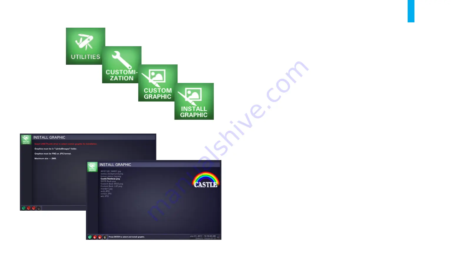
Custom Graphic
utility to install an image that will be displayed on the LCD monitor,
periodically, during the game’s attract mode. The custom image is uploaded or changed using the
Install Graphic
utility.
Note: The image must be loaded onto a USB memory stick, using a separate computer. It must be
in PNG or JPG format and under 2MB in size. Create a folder named “pinballimages” in the root
directory of the USB stick, then copy your graphic(s) into the folder. Power up the game, open the
coin door, and use the diagnostics buttons to enter the
Install Graphic
utility; the LCD monitor will
display the screen shown on the left in figure B34.
Locate the end of the USB extension cable, just inside the open coin door (to the left of the coin
box). Remove the Bluetooth dongle from the connector at the end of the cable and set it aside.
Fully insert the USB stick in its place (if your USB stick is equipped with an “in-use” light, it will
illuminate). The screen on the right in figure B34 will come up automatically, showing a listing of
the available graphics in your USB stick’s “pinballimages” folder.
Use the
Up/+
and
Down/-
buttons to select the graphic you wish to install, then press the
Enter
button to complete the operation.
To exit the
Install Graphic
utility at any time, press the
Back/Escape
button.
If you removed the game's Bluetooth dongle, plug it back into the end of the USB extension cable.
Figure B34. Install Graphic utility screens.
Install Graphic
Summary of Contents for Dialed in!
Page 2: ......
Page 4: ......
Page 15: ...Game Assembly Setup A 1 Game Assembly Setup Section A...
Page 43: ...The Dialed In Menu System B 1 The Dialed In Menu System Section B...
Page 99: ...Game Parts Information C 1 Game Parts Information Section C...
Page 104: ...Game Parts Information C 6 7 9 17 5 4 19 1 2 10 16 13 14 15 8 12 18 11 6 3 20 5 21 23 22...
Page 106: ...Game Parts Information C 8 1 2 3 4 5 6 7 8 9 10 11 12 13 18 15 16 14 17 19 20 22 21...
Page 114: ...Game Parts Information C 16 10 3 11 1 7 7 12 4 6 9 8 8 2 5 8a...
Page 126: ...Game Parts Information C 28 1 4 8 9 3 5 3 2 6 3 7...
Page 130: ...Game Parts Information C 32 7 2 4 8 1 11 3 10 5 6 12 15 9 13 14...
Page 148: ...Game Parts Information C 50 1 2 3 4 5 7 8 9 10 12 12 14 15 6 6 6 6 6 6 6 13 11...
Page 150: ...Game Parts Information C 52 1 2 3 4 5 6 7 8 9 10 12 10 10 10 10 11 11 13...
Page 160: ...Game Parts Information C 62 9 9 1 7 2 4 5 6 6 8 3...
Page 166: ...Game Parts Information C 68 1 2 3 4 5 6 9 10 11 12 13 14 17 19 21 22 26 27 28 35 36...
Page 168: ...Game Parts Information C 70 1 2 3 4 5 6 9 10 11 12 13 14 17 19 21 22 26 27 28 36 35...
Page 170: ...Game Parts Information C 72 41 42 44 45 46 47 48 57 58 59...
Page 172: ...Game Parts Information C 74 57 58 59 41 42 44 45 46 47 48...
Page 208: ...Game Parts Information C 110 1 2 2 2 3 4 5 6 11 9 10 10 10 7 8 12 12 12 13 15 14 16...
Page 210: ...Game Parts Information C 112 1 2 4 5 5 5 3...
Page 212: ...Game Parts Information C 114 1 2 5 6 7 8 4 9 11 10 12 13 14 15 17 17 18 19 20 21 16 24 23 22 3...
Page 222: ...Game Parts Information C 124 4 2 3 1 5...
Page 224: ...Game Parts Information C 126 1 2 3 1 2 3 4 4 5 5 5 5 5 5 5 5 5 5 5 6 6 9 8 10 7 11 13 12...
Page 236: ...Game Parts Information C 138...
Page 237: ...Reference Diagrams Schematics D 1 Reference Diagrams Schematics Section D...
Page 312: ...Reference Diagrams Schematics D 76...
Page 348: ...Reference Diagrams Schematics D 112 1 Fuse Locations In Bottom of Cabinet 4 2 3 In Backbox...
Page 354: ...Reference Diagrams Schematics D 118...
Page 355: ...Game Service Troubleshooting E 1 Game Service Troubleshooting Section E...
Page 367: ...Appendices...


