Game Service & Troubleshooting
E-11
E.7
Replacing Your Game’s CPU Battery
2
2
3
3
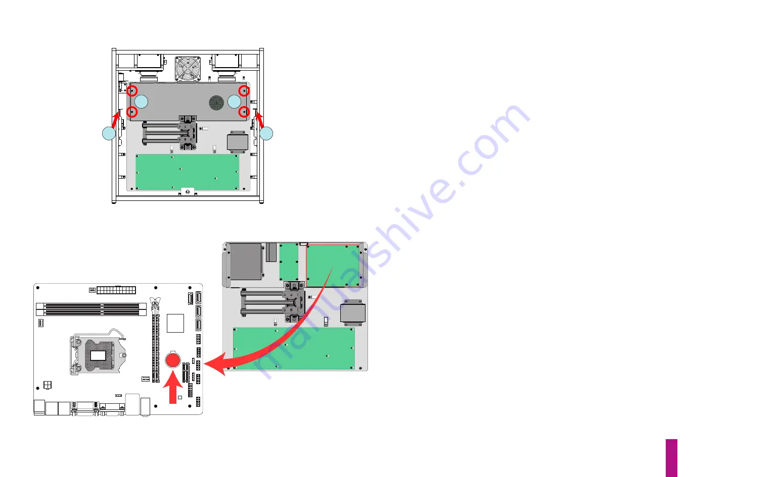
Figure E12. Removing PCB chassis lid.
Your game’s CPU board uses a 3V coin cell, lithium battery (CR2032) to maintain its basic input/out-
put system (BIOS) settings when the game is powered down. If these settings are lost, the CPU will
not boot when the game is powered up. The life expectancy of the CR2032 battery is approximate-
ly three years. It is important to change your game’s CPU battery before it discharges below 3V.
However, in order to preserve the CPU’s BIOS settings, the change must be made while the game is
powered on. A step-by-step process for replacing the battery is provided below.
1)
With the game off, open the coin door and locate the keys to the backbox lock (hanging on a
hook, alongside one of the coin mechanisms). Unlock the backbox lock (item 2 on pg C-45), slide
the backglass upward and remove it, bottom edge first. Carefully set it aside.
2)
Release the 27" LCD monitor, by lifting the two latches, top left & right (red arrows, figure E12),
while carefully pulling the screen straight out of the backbox. Extend the screen outward, then
swing it over to either side of the backbox.
3)
Disconnect the Backbox LED Strip cable (left, inside of the backbox) and free the loose end from
the nylon cable clamp(s). Remove the lid of the Backbox PCBs EMI Shield Enclosure by removing the
four HWH Phillips machine screws (circled in red, figure E13); set the lid and the four screws aside.
4)
Locate the CPU board (upper right corner of the EMI shield enclosure), then the shiny, CR2032
coin cell battery & holder mounted on its surface (red arrow and circle, figure E13). Note the orien-
tation of the battery in its holder (with the battery label/imprint facing
outward
).
5)
Power the game on and wait for it to complete its boot cycle. Cut a 3-inch long piece of masking
tape and fold it 1 inch from the end. This should form a 1-inch long “handle” and leave a 1-inch
long adhesive end.
6)
Briefly touch the lockdown bar on the game to dissipate any static charge in your body
before
touching the CPU board.
7)
Carefully affix the adhesive portion of the tape onto the top of the CR2032 battery, applying
moderate pressure.
WARNING
: Do
not
flex the CPU circuit board! Rub the surface of the tape,
back and forth, to ensure that it attaches well to the battery -
not
the holder.
Figure E13. CPU board and battery locations.
Summary of Contents for Dialed in!
Page 2: ......
Page 4: ......
Page 15: ...Game Assembly Setup A 1 Game Assembly Setup Section A...
Page 43: ...The Dialed In Menu System B 1 The Dialed In Menu System Section B...
Page 99: ...Game Parts Information C 1 Game Parts Information Section C...
Page 104: ...Game Parts Information C 6 7 9 17 5 4 19 1 2 10 16 13 14 15 8 12 18 11 6 3 20 5 21 23 22...
Page 106: ...Game Parts Information C 8 1 2 3 4 5 6 7 8 9 10 11 12 13 18 15 16 14 17 19 20 22 21...
Page 114: ...Game Parts Information C 16 10 3 11 1 7 7 12 4 6 9 8 8 2 5 8a...
Page 126: ...Game Parts Information C 28 1 4 8 9 3 5 3 2 6 3 7...
Page 130: ...Game Parts Information C 32 7 2 4 8 1 11 3 10 5 6 12 15 9 13 14...
Page 148: ...Game Parts Information C 50 1 2 3 4 5 7 8 9 10 12 12 14 15 6 6 6 6 6 6 6 13 11...
Page 150: ...Game Parts Information C 52 1 2 3 4 5 6 7 8 9 10 12 10 10 10 10 11 11 13...
Page 160: ...Game Parts Information C 62 9 9 1 7 2 4 5 6 6 8 3...
Page 166: ...Game Parts Information C 68 1 2 3 4 5 6 9 10 11 12 13 14 17 19 21 22 26 27 28 35 36...
Page 168: ...Game Parts Information C 70 1 2 3 4 5 6 9 10 11 12 13 14 17 19 21 22 26 27 28 36 35...
Page 170: ...Game Parts Information C 72 41 42 44 45 46 47 48 57 58 59...
Page 172: ...Game Parts Information C 74 57 58 59 41 42 44 45 46 47 48...
Page 208: ...Game Parts Information C 110 1 2 2 2 3 4 5 6 11 9 10 10 10 7 8 12 12 12 13 15 14 16...
Page 210: ...Game Parts Information C 112 1 2 4 5 5 5 3...
Page 212: ...Game Parts Information C 114 1 2 5 6 7 8 4 9 11 10 12 13 14 15 17 17 18 19 20 21 16 24 23 22 3...
Page 222: ...Game Parts Information C 124 4 2 3 1 5...
Page 224: ...Game Parts Information C 126 1 2 3 1 2 3 4 4 5 5 5 5 5 5 5 5 5 5 5 6 6 9 8 10 7 11 13 12...
Page 236: ...Game Parts Information C 138...
Page 237: ...Reference Diagrams Schematics D 1 Reference Diagrams Schematics Section D...
Page 312: ...Reference Diagrams Schematics D 76...
Page 348: ...Reference Diagrams Schematics D 112 1 Fuse Locations In Bottom of Cabinet 4 2 3 In Backbox...
Page 354: ...Reference Diagrams Schematics D 118...
Page 355: ...Game Service Troubleshooting E 1 Game Service Troubleshooting Section E...
Page 367: ...Appendices...


