The Dialed In Menu System
B-21
Camera Test
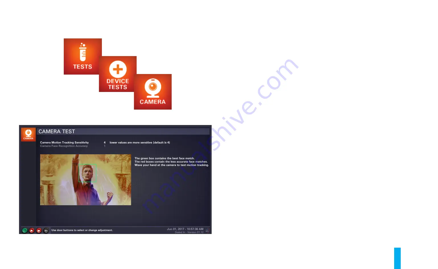
When you enter the
Camera Test
, the LCD monitor will display a screen similar to that shown in
figure B21. A large window on the left side of the screen will show what the game's camera (in the
lower, center area of the backbox) currently "sees". Within that window, a green box will be placed
around (what the software determines to be) the "best match" for a person's face. Red boxes will
be placed around (what the software determines to be) "less accurate" face matches. You can wave
your hand around to test motion detection. When the software recognizes your hand moving, the
words "MOTION DETECTED" will appear, in green, in the center of the screen.
You select a sensitivity control to adjust (motion tracking or face recognition) with the
Up/+
and
Down/-
buttons. The currently selected control will be highlighted in white text. To make a
change, press the
Enter
button, then use the
Up/+
and
Down/-
buttons to specify a new numeric
value. You are providing relative sensitivity levels for the software to use to recognize faces and
detect motion. The game software will apply these levels to the camera image data during game
play in order to implement special features. Once you’re finished adjusting a numerical value, press
the
Enter
button once again to apply the change. To cancel the change, press the
Back/Escape
button.
To exit the
Camera Test
at any time, press the
Back/Escape
button.
Figure B21. Camera Test screen.
Summary of Contents for Dialed in!
Page 2: ......
Page 4: ......
Page 15: ...Game Assembly Setup A 1 Game Assembly Setup Section A...
Page 43: ...The Dialed In Menu System B 1 The Dialed In Menu System Section B...
Page 99: ...Game Parts Information C 1 Game Parts Information Section C...
Page 104: ...Game Parts Information C 6 7 9 17 5 4 19 1 2 10 16 13 14 15 8 12 18 11 6 3 20 5 21 23 22...
Page 106: ...Game Parts Information C 8 1 2 3 4 5 6 7 8 9 10 11 12 13 18 15 16 14 17 19 20 22 21...
Page 114: ...Game Parts Information C 16 10 3 11 1 7 7 12 4 6 9 8 8 2 5 8a...
Page 126: ...Game Parts Information C 28 1 4 8 9 3 5 3 2 6 3 7...
Page 130: ...Game Parts Information C 32 7 2 4 8 1 11 3 10 5 6 12 15 9 13 14...
Page 148: ...Game Parts Information C 50 1 2 3 4 5 7 8 9 10 12 12 14 15 6 6 6 6 6 6 6 13 11...
Page 150: ...Game Parts Information C 52 1 2 3 4 5 6 7 8 9 10 12 10 10 10 10 11 11 13...
Page 160: ...Game Parts Information C 62 9 9 1 7 2 4 5 6 6 8 3...
Page 166: ...Game Parts Information C 68 1 2 3 4 5 6 9 10 11 12 13 14 17 19 21 22 26 27 28 35 36...
Page 168: ...Game Parts Information C 70 1 2 3 4 5 6 9 10 11 12 13 14 17 19 21 22 26 27 28 36 35...
Page 170: ...Game Parts Information C 72 41 42 44 45 46 47 48 57 58 59...
Page 172: ...Game Parts Information C 74 57 58 59 41 42 44 45 46 47 48...
Page 208: ...Game Parts Information C 110 1 2 2 2 3 4 5 6 11 9 10 10 10 7 8 12 12 12 13 15 14 16...
Page 210: ...Game Parts Information C 112 1 2 4 5 5 5 3...
Page 212: ...Game Parts Information C 114 1 2 5 6 7 8 4 9 11 10 12 13 14 15 17 17 18 19 20 21 16 24 23 22 3...
Page 222: ...Game Parts Information C 124 4 2 3 1 5...
Page 224: ...Game Parts Information C 126 1 2 3 1 2 3 4 4 5 5 5 5 5 5 5 5 5 5 5 6 6 9 8 10 7 11 13 12...
Page 236: ...Game Parts Information C 138...
Page 237: ...Reference Diagrams Schematics D 1 Reference Diagrams Schematics Section D...
Page 312: ...Reference Diagrams Schematics D 76...
Page 348: ...Reference Diagrams Schematics D 112 1 Fuse Locations In Bottom of Cabinet 4 2 3 In Backbox...
Page 354: ...Reference Diagrams Schematics D 118...
Page 355: ...Game Service Troubleshooting E 1 Game Service Troubleshooting Section E...
Page 367: ...Appendices...


