Version 2.04
| Optidrive ODP-2 Solar Pump User Guide |
37
www.invertekdrives.com
Par
Parameter Name
Default
Typical
P8-14 Standby Mode
0
0
Set this parameter to 0 if you require the drive to go into Standby mode based on the description in P3-14 above.
P2-27
Standby Activation Delay Time
0
10
This parameter defines the time period, whereby if the drive operates at the frequency / speed set in P3-14 (Standby speed
threshold) for greater than the set time period, the Optidrive output will be disabled, and the display will show
. The
function is disabled if P2-27 = 0.0.
Please note that changes made to P8-15 can affect the Standby Mode operation.
P8-13 Low power restart delay
0
300
This parameter can be used to limit the drive from starting and stopping the pump repeatedly after collapsing the array at times of very
low irradiance when the drive is used in PID mode for pressure regulation. This function is disabled when the parameter is set to 0s. The
function works by entering a ‘Low Power Standby’ mode if the array voltage (DC Bus voltage) drops below the value set in P8-18 and
will sit in this state and not attempt a restart until the time set in this parameter has elapsed.
When in this Standby mode, the LED display will indicate
oP
and the OLED/TFT display will indicate Low Power Standby.
Bit 15 in the status word will go high to indicate that this mode is active.
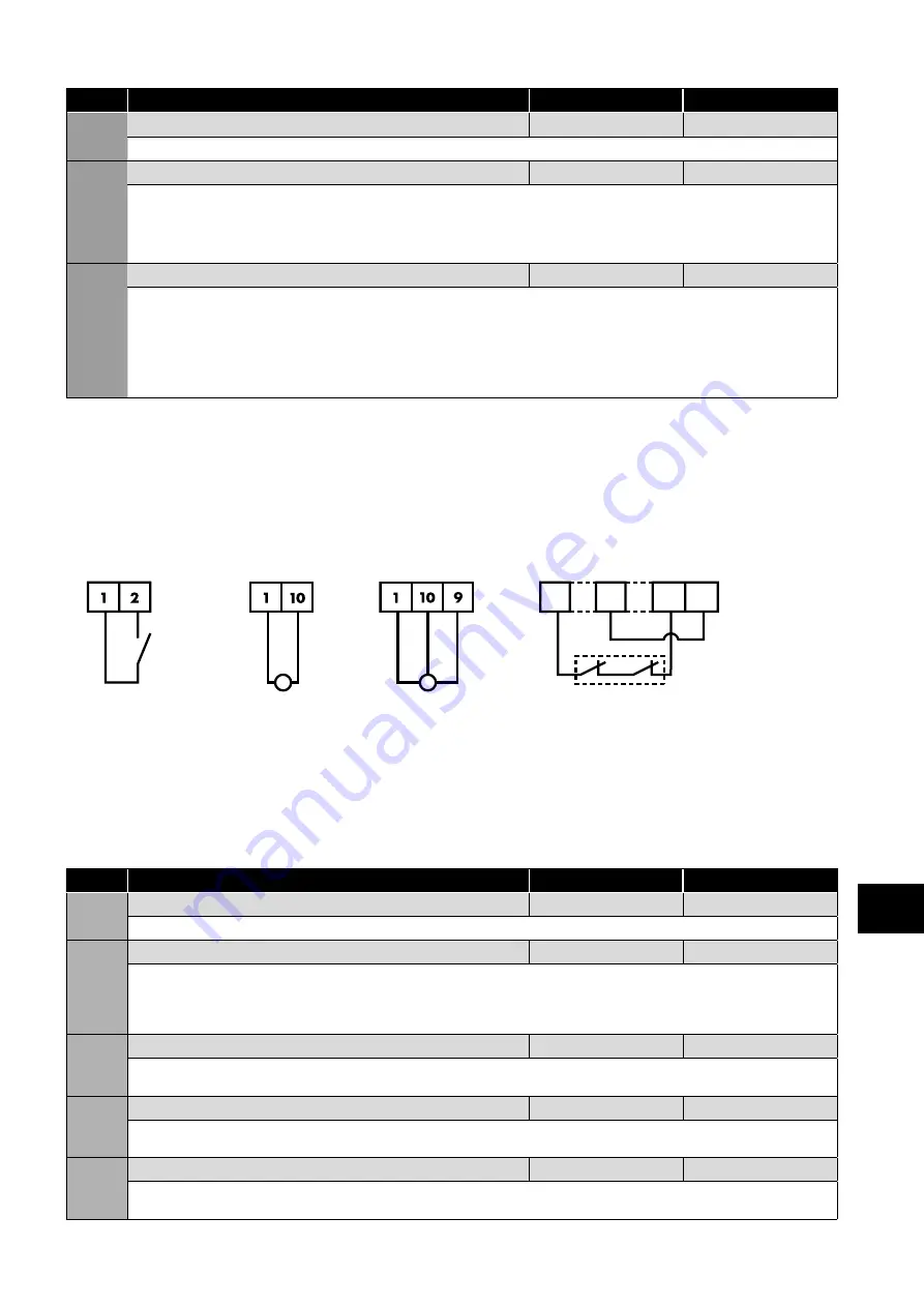
6.2.7. Minimum control wiring requirements for pressure control
The P2 Solar Pump Drive is a very flexible product which can be controlled in a number of ways. In order to operate the drive as
detailed in section
, the drive will need the STO circuit to be closed (see section
)
and a drive enable provided to Digital Input 1 as shown below. Please note that if the STO function is not going to be used in the
application, the wiring is still required and a link will be needed between terminals T1-T12 and T9-T13.
Minimum Control wiring required for pressure control
Start/Stop
Pressure Feedback
Mandatory Hardware Enable
Or
1
9
12 13
Link T1 to T2 to start
and open to stop
Loop-powered
transducer
3-wire
transducer
The STO inputs can be used as a high
integrity means of preventing torque
being applied on the motor – section
. If this function
is not required, the terminals must be
linked as illustrated.
6.2.8. Parameter Settings for Optional Irradiance Sensor
Par.
Description
Default
Typical
P2-30
Analogue Input 1 Format
0-10V/4-20mA
-
This parameter defines the type of signal from the irradiation sensor.
P8-14
Standby Mode
0
2
This parameter selects the variables that causes the drive to go into standby (sleep) mode. By default, this parameter is set to 0 which
means that standby mode is selected based on pump speed. A setting of 1 however, configures the drive to go into standby mode
and ‘wake-up’ from this condition based on the voltage of the DC Bus.
If a solar irradiation sensor is used then this setting should be changed to 2.
P8-15
Standby Activation Level
0.0%
45.0%
This parameter sets the irradiation level in % of transducer range, below which the drive will decelerate the pump speed and enter
Standby (sleep) mode.
P8-16
Standby Wake-Up Level
0.0%
53.0%
This parameter sets the irradiation level in % of transducer range, above which the drive will exit standby (sleep) mode, start the pump
and increase the speed.
P8-17
Standby Wake-Up Delay Time
0
30s
This parameter sets the delay time in seconds, which the standby wake-up condition must be present for before the drive will begin the
wake-up sequence and exit standby (sleep) mode.
6
Quick Star
t Pr
ocedure


