58
| Optidrive ODP-2 Solar Pump User Guide |
Version 2.04
www.invertekdrives.com
Par.
Function
Setting Range
Default
Notes
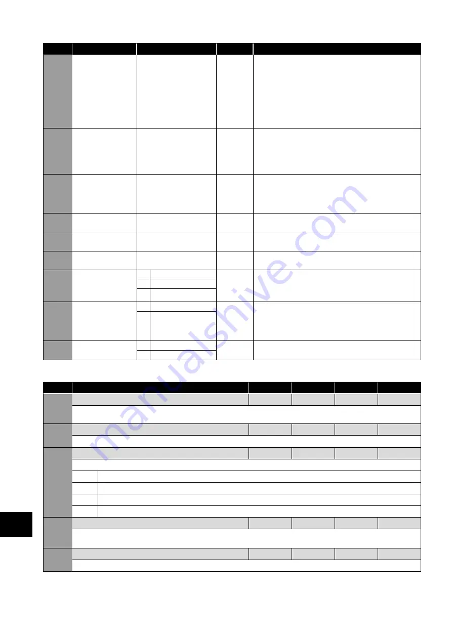
P7-09
Over Voltage Current
Limit
0.0 – 100.0%
5.0%
Effective in vector speed control mode only, and will come
into function once the drive DC bus voltage increases above a
preset limit. This voltage limit is set internally just below the over
voltage trip level. This parameter will effectively limit the output
torque current in order to prevent a large current flowing back
to the drive, which may cause an Over-voltage trip. A small
value in this parameter will limit the motor control torque when
the drive DC bus voltage exceeds the preset limit. A higher
value may cause a significant distortion in the motor current,
which may cause an aggressive, rough motor behaviour.
P7-10
System Inertia
Constant
0 - 600
10
System Load Inertia to Motor Inertia Ratio entered as H = (JTot
/ JMot). This value can normally be left at the default value
(10) and is used by the drive control algorithms as a feed-
forward control variable to provide optimum torque current to
accelerate the load. Hence accurate setting of the inertia ratio
will produce a better system response and dynamic behaviour.
P7-11
Pulse Width Minimum
Limit
0 - 500
This parameter is used to limit the minimum output pulse
width, which can be used for long motor cable applications.
Increasing the value of this parameter will reduce the risk of
over-current trips, but will also reduce the maximum available
output motor voltage.
P7-12
Magnetising Period
0 – 5000ms
Drive
Dependent
Sets the motor magnetising period in V/F Mode.
Sets the motor alignment time in PM modes.
P7-14
Low Frequency Torque
Boost Current
0.0 – 100.0%
0.0%
For PM Motors, applies a torque boost current at low
frequency, % x P1-08.
P7-15
Low Frequency Torque
Boost Frequency Limit
0.0 – 50.0%
0.0%
For PM motors, determines the frequency, % x P1-09 when the
boost current is removed.
P7-18
Over-modulation
Enable
0
Disable
0
When enabled, over modulation provides a small increase in
the available output voltage from the drive, which can assist in
applications where the supply voltage is too low to provide the
required motor voltage, resulting in an increased motor current.
1
Enable
2
Auto
P7-19
BLDC Light Load
Optimization
0
Disable
1
When enabled and the drive is set in BLDC Mode (P4-01
= 4), the drive will reduce the output voltage during light
load operation in order to improve motor efficiency and
performance. This setting has no effect when the motor is
significantly loaded.
1
Enable
P7-20
Modulation Mode
0
3-Phase Modulation
0
1
2-Phase Modulation
9.5.3. Parameter Group 8 – Application Parameters
Par
Name
Minimum
Maximum
Default
Units
P8-01
Pump Stir Interval Duration
0
60000
0
Minute
Sets the duration that the drive will remain in ‘standby’ for before it activates a stir profile. Setting this value to zero disables the pump
stir function.
P8-02
Pump Stir Activation Time
1
6000
10
s
Sets the time duration for the stir cycle once activated.
P8-03
Pump Clean Function Select
-
-
-
-
Determines the conditions that trigger the pump clean cycle.
0
Disabled
1
Active on start-up
2
Active on start-up and over-torque detection
3
Active on over-torque detection only
P8-04
Pump Clean Duration
0
600
0
Seconds
Sets the time period for the operation of the pump clean cycle. If bi-directional pump cleaning is used, this duration will be used twice –
once in the reverse direction and once again in the positive direction.
P8-05
Pump Clean Function Ramp Time
0
6000
30
Seconds
Acceleration ramp that is used only during a pump clean cycle.
9
Extended P
arameters


