36
| Optidrive ODP-2 Solar Pump User Guide |
Version 2.04
www.invertekdrives.com
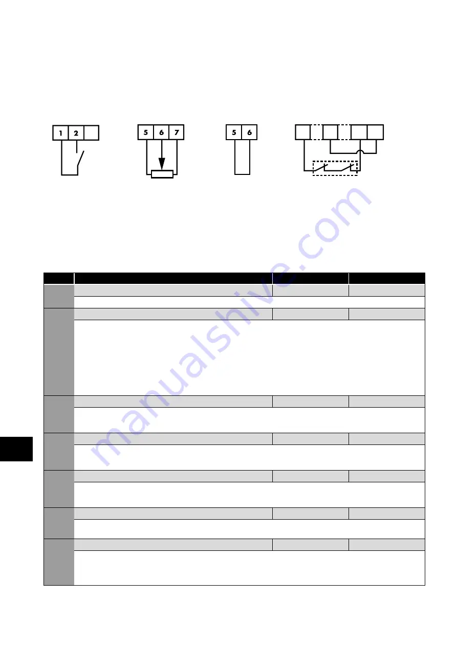
6.2.5. Minimum control wiring requirements for basic operation
The P2 Solar Pump Drive is a very flexible product which can be controlled in a number of ways. In order to operate the drive as
detailed in section
, the drive will need the STO circuit to be closed (see section
and a drive enable provided to Digital Input 1 as shown below. Please note that if the STO function is not going to be used in the
application, the wiring is still required and a link will be needed between terminals T1-T12 and T9-T13.
Minimum Control wiring required for basic operation
Start/Stop
Speed Reference
Mandatory Hardware Enable
3
Or
1
9
12 13
Link T1 to T2 to start
and open to stop
Potentiometer
Maximum
possible
The STO inputs can be used as a high
integrity means of preventing torque
being applied on the motor – section
. If this function
is not required, the terminals must be
linked as illustrated.
6.2.6. Additional settings for pressure regulation (PID)
Par
Parameter Name
Default
Typical
P1-12 Enable PID mode for pressure control
0 (Terminal)
3 (PID)
Set the drive into PID mode for pressure control.
P2-33
Analog Input 2 (Terminal 10) Format
-
= 0 to 10 Volt Signal (Uni-polar).
= 10 to 0 Volt Signal (Uni-polar).
P
= Motor PTC Thermistor Input.
= 0 to 20mA Signal.
= 4 to 20mA Signal, the Optidrive will trip and show the fault code
if the signal level falls below 3mA.
= 4 to 20mA Signal, the Optidrive will ramp to stop if the signal level falls below 3mA.
= 20 to 4mA Signal, the Optidrive will trip and show the fault code
if the signal level falls below 3mA.
= 20 to 4mA Signal, the Optidrive will ramp to stop if the signal level falls below 3mA.
P3-01
PID Proportional Gain
1.0
-
PID Controller Proportional Gain. Instantaneous error between the feedback and the set-point in the PID controller is multiplied by
P3-01 to produce the output from the PID controller. Higher values of proportional gain produce a larger change in the drive output
frequency in response to changes in the PID set-point or feedback signals. Too high a value can cause instability.
P3-02
PID Integral Time
1.0
-
PID Controller Integral Time. Accumulated error in the PID control. Uses accumulated errors between set-point and feedback signals
to influence the output from the PID controller. P3-02 is the time constant for accumulating error. Larger values provide a more damped
response. Lower values result is a faster system response but may result in instability.
P3-06
PID Digital Reference Value
0.0
-
This digital reference is used as the setpoint for the PID. The units are in % and this refers to the percentage of the full scale range of the
feedback transducer used. For example, if a 0 – 10 bar transducer is used, the range is 10 bar (10-0) and if 4.5 bar is the required set-
point, this parameter should be set to 45% (4.5 / 10 x 100%).
P3-13
PID Restart Error Level
5.0
5.0
Sets a programmable PID Error Level whereby if the drive enters standby mode whilst operating under PID control, the difference
between the PID reference and PID feedback signals must exceed this error level to restart the PID controller.
P3-14
Standby Activation Speed
0.0
-
This value should be the no-flow speed of the pump. This can be identified by running the pump in PID mode modulating to the
pressure and then slowly closing a valve on the pump output (the other side of the pressure transducer) to get to a point of no flow.
The no flow speed is the speed that the pump will settle to and maintain the set pressure. It is always best to add a couple of Hz onto
this no flow speed to ensure that the pump doesn’t sit there just above the standby speed threshold.
6
Quick Star
t Pr
ocedure


