


Chapter 4: Operating Instructions
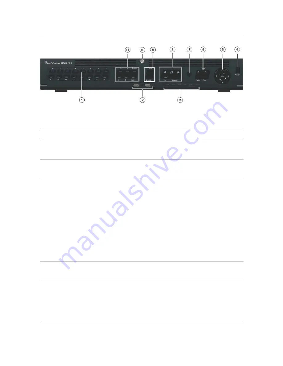
Figure 7:
Fro
nt panel
16-channel model:
The controls on the front panel include:
Table 2: Front Panel Elements
Item
Name
Description
1.
Channel buttons
Switch between different cameras in live, PTZ control or
playback modes.
Use the soft keyboard to enter numerals 0 to 9.
2.
USB Interfaces
Universal Serial Bus (USB) ports for additional devices such as
a USB mouse, CD/DVD burner, and USB Hard Disk Drive
(HDD).
3.
Status LEDs
Power
: A flashing green light indicates the recorder is working
correctly. Red indicates a fault.
Alarm
: A steady red light indicates that there is a sensor Alarm
In or another alarm such as motion or tampering. A steady green
light means there is no alarm.
Tx/Rx
: Flashing green indicates a normal network connection.
No light indicates that it is not connected to a network.
HDD
: HDD indicator blinks red when data is being read from or
written to the HDD. A steady red light indicates an HDD
exception or error.
Ready
: A steady green light indicates that the recorder is
functioning properly.
Archive
: Blinking green indicates archiving is in progress.
4.
Archive button
Press once to enter quick archive mode. Press twice to start
archiving. Indicator blinks green when data is being written to
backup device.
5.
Direction
The DIRECTION buttons are used to navigate between different
fields and items in menus.
Enter button
The ENTER button is used to confirm selection in any of the
menu modes.
See Table 3 on page 19 for a detailed description of these
buttons by different tasks.
6.
PTZ buttons
Zoom +/-
: In live view mode, playback mode, and PTZ control
mode use this button to zoom in and out. Also use them to
TruVision NVR 21 (SP) User Manual
17


