11
• DOK-POWER*-TVD*1.3****-ANW1-EN-E1,44 • 02.97
P
DC
P
KB-3
P
KB-03
P
BD
P
BM
W
max
P
m
P
mKB-3
P
mKB-03
TVD 1.3
Power conn.
Auxiliary bleeder
kW
kW
kW
kW
kW
kWs
kW
kW
kW
module
module
7,5
15
22,5
0.5
20
30
6
12
18
-08-03
NAM 1.3-08
---------------------
7,5
15
22,5
1.5
60
130
6
12
18
-08-03
NAM 1.3-08
TBM 1.2-40-W1
15
30
45
1.0
40
60
12
24
36
-15-03
NAM 1.3-15
---------------------
15
30
45
2.0
80
160
12
24
36
-15-03
NAM 1.3-15
TBM 1.2-40-W1
2. Range of Applications
2.2. Power ratings of the TVD 1.3
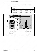
The TVD 1.3 is available with a DC bus continuous power of 7.5 kW and 15
kW. It can be combined with an auxiliary bleeder module. This means that the
power supply can be optimally matched to the requirements of the respective
application.
Power supply components
Fig. 2.2:
Power ratings in the TVD 1.3
2.3. Overload Capabilities of the TVD 1.3
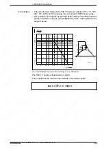
The TVD 1.3 can be overloaded for a short duration for the purpose of
accelerating feed and spindle drives.
The maximum acceleration ratings must be taken into account
during project planning and may not be exceeded!
Power limit
ON time t/s
Load P/%
100
200
300
0.3
3
10
Peak power for 0.3 s to
accel feed drives
Short-term operating power for 3 s
to accelerate the spindle drives
Continuous power for ON time
exceeding 10 s
TVRBelastungsdiagr
Fig. 2.3: Load diagram - TVD 1.3
(1) P
DC
= continuous DC bus power
(6) W
max
= maximum regenerated energy
(2) P
KB-3
= DC bus short-term power for
(7) P
m
= mechanical output for ON time of
3s (accel. of spindle drive)
> 10s
(3) P
KB-03
= DC bus peak power for
(8) P
mKB-3
= mechanical short-term output for
0.3s (accel. feed drives)
3s (accel. of spindle drive)
(4) P
BD
= Bleeder continuous power
(9) P
mKB-03
= mechanical peak output for
0.3s (accel. feed drives)
(5) P
BM
= Bleeder peak power
(1)
(2)
(3)
(4)
(5)
(6)
(7)
(8)
(9)


