42
• DOK-POWER*-TVD*1.3****-ANW1-EN-E1,44 • 02.97
4. TVD 1.3 Interconnections
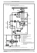
4.5. TVD interconnect for a position-controlled braking
of the drives
Drives which are coupled electronically as if by gearboxes under the control
of an NC cannot normally accept an angular positioning error in the event of
a power failure.
The NCB link on the TVD (X3/1 - X3/2) must be jumpered. The mains
contactor may not switch the drive enable signal off.
The DC bus voltage is not short-circuited so that energy is available for a
position-controlled stopping of the drives.
During E-stop or if one of the monitor circuits of the TVD, e.g., during a power
failure, is tripped, then the drives will be brought to a standstill under position-
control through the NC.
The energy stored in or regenerated to the DC bus circuit must be greater than
the energy required to excite the inductance machines or for return movements.
When the E-stop chain opens, the main contactor in the TVD drops out
immediately. The NC must bring the drives to a stop under position control.
Application
Source of danger:
A faulty power supply is not signalled to the drives when the NCB link
is installed.
Possible consequences:
There is an uncontrolled braking of the drives with a power failure.
The degree of damage depends upon the type of machine.
How to avoid:
If the UD contact opens, then the NC must bring the drives to a
position-controlled standstill.
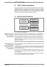
Caution !
OFF
ON
K1
(X5/3-4)
DC bus
voltage
UD contact
Drive enable from
the control unit
t
1
≥
200 ms; t
2
= 1.25 ... 1.4 s; t
3
≥
40 ms
t
3
t
2
t
2
t
1
t
1
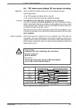
1) Do not switch drive enable signal off until the drives are standing stil.
1)
SVTVDzLBA
Fig. 4.8: Signal path when switching on a TVD
Features
Mode of operation


