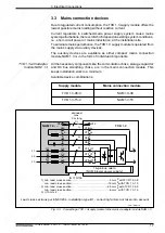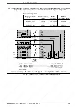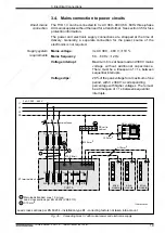
23
• DOK-POWER*-TVD*1.3****-ANW1-EN-E1,44 • 02.97
3.7. Commutation choke
In an effort to keep system perturbations as low as possible, the TVD should
always be operated with a commutation choke. See sections 3.3 and 3.4; for
power loss see dimension sheet in section 7.
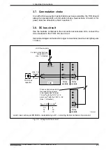
3.8. DC bus circuit
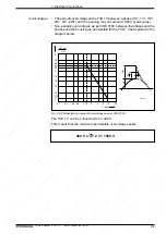
Use the busbars contained in the connection accessories kit to connect the
drive modules to the TVD's DC bus circuit.
Use twisted single conductors for longer connections (maximum length equals
1 meter).
3. Electrical Connections
1L+ 1L-
L-
L+
L-
L+
L-
L+
L-
L+
max. 1 m
twisted
10 mm2
C1-DC bus
capacitor
L1-DC bus reactor
Cross section depends on
the peak DC bus power
to be transmitted. At least
10 mm
2
with the TVD 1.3-15
and 4 mm
2
with the TVD 1.3-08
(max. 1 m twisted).
PDC in kW
7,5
14
15
A in mm2
4
10
16
TVRZwkreis
TVD
Drive
module
Drive
module
Drive
module
Lead cross section per EN 60204 - installation type B1 - correcting factors not taken into account
For lead cross sections
see section 3.3
max. 1 m twisted
Fig. 3.9:
Wiring the DC bus circuit


