46
• DOK-POWER*-TVD*1.3****-ANW1-EN-E1,44 • 02.97
5. Terminal Descriptions
5.5. Signal Voltages
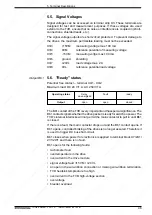
Signal voltages can be accessed on terminal strip X3. These terminals are
designed for test and measurement purposes. If these voltages are used
exterior to the TVD, ensure that no noise or interference is coupled in (short-
connections, shielded leads, etc.).
The signal voltage outputs are short-circuit protected. To prevent damage to
the drives, the maximum permissible loading must not be exceeded.
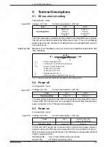
X3/3
+15VM
measuring voltage max.100 mA
X3/4
0VM
reference potential of measuring voltage
X3/5
-15VM
measuring voltge max.100 mA
X3/6
ground
shielding
X3/7
+24VL
load voltage max. 2 A
X3/8
0VL
reference potential load voltage
5.6. "Ready" status
Potential free contact – terminal X4/1 - X4/2
Maximum load: DC 24 V/1 A; AC 250 V/1A
Output Bb1
Operating status
Relay
Fault
ready
de-energized
Output
open
open
closed
The Bb1 contact of the TVD is very important and has special significance. The
Bb1 contact signals whether the drive packet is ready for swtich on power. The
TVD's internal interlocks will not permit the main contactor to pull in until Bb1
is closed.
If there is a fault, the main contactor drops out and the Bb1 contact opens. If
Bb1 opens, controlled braking of the drives is no longer assured. Therefore it
is used to trigger DC bus short-circuit.
Bb1 closes when power for electronics is applied to terminal block X7/2U1/
2V1/2W1 and there is no fault.
Bb1 opens for the following faults:
• tachometer fault
• overtemperature in the drive
• overcurrent in the drive module
• signal voltage fault
±
15 VM / +24 VL
• an open in the wire-ribbon connection or missing wire-ribbon termination
• TVD heatsink tempreature too high
• overcurrent in the TVD high-voltage section
• overvoltage
• bleeder overload


