16
• DOK-POWER*-TVD*1.3****-ANW1-EN-E1,44 • 02.97
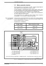
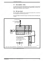
3.2. TVD 1.3 interconnect diagram with individual,
additional components
3. Electrical Connections
L-
L+
+ -
2
X 7
R2
X16
UD
BB
+15V
0VM
-15V
+24V
0VL
UESS
shield
Bb1
UD
BVW
TVW
ZKS
ZKS
OFF
OFF
ON
ON
+15VM
0VM
-15VM
3xAC (380 - 480) V
(50 - 60) Hz
PE
L3
L2
L1
power
supply
electronics
supply
2U1
2V1
2W1
1U1
1V1
1W1
EPU+
EPU -
PE
K1
1
2
3, 4
5, 6, 7, 8
9, 10
11, 12
13, 14
15
16
NCB
X 2
X 3
X 4
X 5
X 12
X 9
X1
Q1
K1
K1
1L+
2L+
EB
IB
RB1
RB2
1
2
3
4
5
6
1
2
3
4
5
6
7
8
1
2
3
4
C1
R1
EB
C2
TBM
U1
W1
V1
U2
W2
V2
1
X7/EB
L-
L+
L2
X 8
X 7
+24V 0V
X15
12
TVD 1.3
Power supply module for direct connection
- with built-in bleeder
- with regulated DC bus
central grounding point
for all drive modules
Power
supply
for
AC
drives
and/or
main
spindle
drives
DC 300V
conductor rails
Electronics
power
supply
,
signal
exchange,
16-pin
bus
connection
ready
bleeder prewarning
temp. prewarning
acknowledge power of
f
acknowledge power on
ZKS
OFF
ON
Options
R1 - bleeder
, ext. mounting
R2 - auxiliary bleeder module
TBM
C1 - additional electronics backup
C2 - additional power backup
max. 2
A
NC controlled braking
max. 100 mA
power voltage ok
BR1 - bridge for switching
the bleeder
C3 - Buf
fer capacitance
L1 - DC bus smoothing reactor
L2 - commutating reactor
T
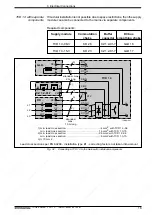
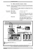
erminal diagram for Supply Module TVD 1.3 with Individual Components
with 380 ... 480V mains connection for power and electronics - internal power switch
1
2
3
4
5
6
+24V
0VL
7
8
BR1
- +
for TBM
with
DC 24V blower
power source
TVD/KompAnschlpl
L1
P
N
P
N
C3
shield
Fig. 3.2:
Interconnect diagram of TVD 1.3 supply module with individual additonal
components


