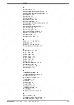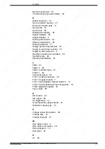
64
• DOK-POWER*-TVD*1.3****-ANW1-EN-E1,44 • 02.97
7. Dimensional data
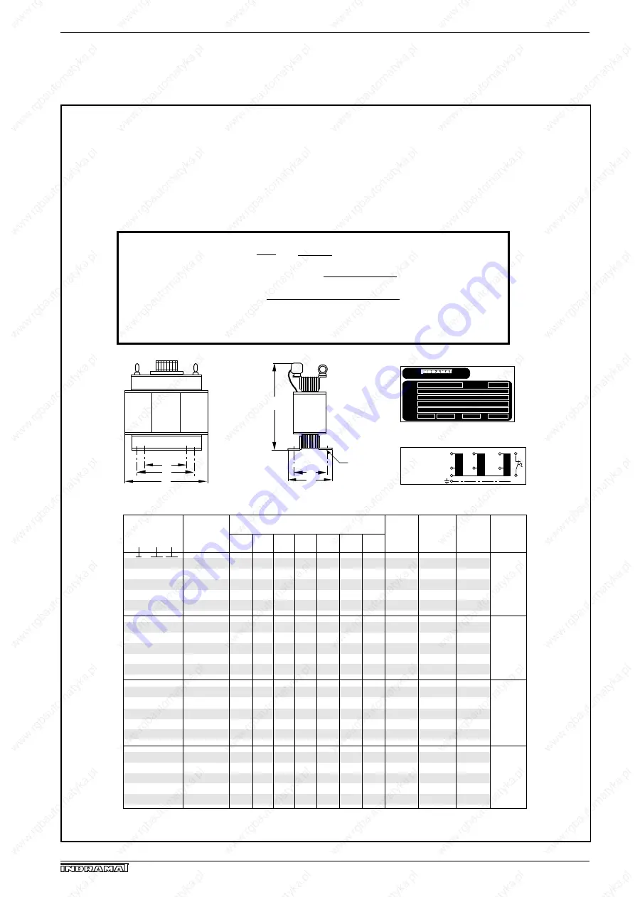
Fig. 7.9: DST autotransformers
4/S/240-460
7.5/S/240-460
12.5/S/240-460
25/S/240-460
50/S/240-460
4/S/580-460
7.5/S/580-460
12.5/S/580-460
25/S/580-460
50/S/580-460
4/S/500-460
7.5/S/500-460
12,5/S/500-460
25/S/500-460
50/S/500-460
4/S/690-460
7.5/S/690-460
12.5/S/690-460
25/S/690-460
50/S/690-460
A
240
335
360
480
580
240
240
300
360
420
180
205
240
300
335
240
300
335
420
480
B
150
175
190
195
265
130
140
155
190
215
105
130
140
155
175
140
155
175
205
222
C
260
365
395
500
540
260
260
325
395
450
190
210
260
325
365
260
325
365
450
500
D
170
230
250
356
400
170
170
210
250
280
125
145
170
210
230
170
210
230
280
356
E
110
160
170
-----
270
110
110
140
170
190
80
95
110
140
160
110
140
160
190
-----
F
120
145
160
158
215
100
110
125
160
155
75
95
110
125
145
110
125
145
145
185
G Ø
11
11
11
13
18
11
11
11
11
14
7
7
11
11
11
11
11
11
14
13
24.5
55
70
135
195
18
22
37
72
95
8.5
13
22
36
53
22
37
57
88
178
10
10
10
35
70
4
4
10
10
35
4
4
10
16
35
10
10
10
16
35
120
225
310
500
750
140
260
375
625
1000
160
260
440
750
1050
140
225
375
500
750
Dimensional table:
Type
DST
200…240V
480…580V
480…500V
570…690V
Primary or
input
voltage
(
±
10%)
Weight
kg
Clamps
mm
2
Power
dissip.
W
Dim. in mm
MBDSTsteh
Trans-
mission
ratio
ü = 0.52
ü = 1.26
ü = 1.09
ü = 1.5
1)
2)
3)
1) Nominal power n kVA 2) max. nominal input voltage in V 3) max. nominal output voltage in V
Type plate: example
Circuits:
overvoltage
U2
U1
N
V2
V1
W2
W1
undervoltage
a
b
*) max. Belastung: DC 24V/1A; AC 230V/1A
*
F
B
E
D
A
G
C
GmbH D 97816 Lohr a. M.
Type
Prim.
Sec.
S
DST 20/S/580 - 480 Bj. 1993
480 … 580 V
380 … 460 V 30 … 25 A
20 kVA YNa0 T 40/B f 50/60 Hz
P
DC
= DC bus cont. power in W
S
AN
= connectefd load in VA
P
DC
•
√
(3 x 417 V)
25.5
U
2
= = = 417 V
U
1
525 V
ü 1.26
S
AN
=
As a result of the broad input voltage range, the TVD 1.3 can be attached to most internationally used power
systems without the use of a transformer. With mains rated voltages of < 380 V or > 480 V a transformer is
required. The following transformers can be used in conjunction with the TVD 1.3 for rated mains voltage as listed
in column 2 of the table. A special transformer type or transformer connection for each mains voltage is not
required.
The connected load for the TVD 1.3 is dependent upon the voltage. When calculating the connected load take
the output voltage of the mains transformer into account.
Example: mains voltage or transformer inputv oltage = U
1
= 525 V, ratio = ü = 1.26
7.9. DST Autotransformers with a secondar or output
voltage of 380...460 V

