25
• DOK-POWER*-TVD*1.3****-ANW1-EN-E1,44 • 02.97
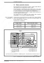
3.12. Additional bleeder module TBM
3. Electrical Connections
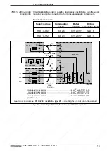
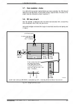
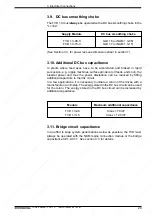
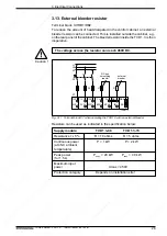
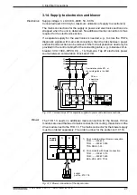
The TVD 1.3 can be operated with an additional bleeder module of the TBM
1.2 type. The TVD and TBM combination gives the following power data:
(1)
(2)
(3)
Supply
Additional bleeder
P
BD
P
BM
W
max
module
module
kW
KW
kWs
TVD 1.3-08
TBM 1.2-040-W1
1.5
60
130
TVD 1.3-15
TBM 1.2-040-W1
2.0
80
160
(1) P
BD
= Continuous bleeder power
(2) P
BM
= Peak bleeder power
(3) W
max
= Maximum regenerated energy
In a worst case scenario, the sum of the peak regenerated power of
all simultaneously braking servo drives may not exceed the peak
bleeder power of the supply module. If such is not taken into
account during system design, then it is possible that the DC bus
voltage during an E-stop could climb to high to the point where the
drive equipment could be damaged.
Caution !
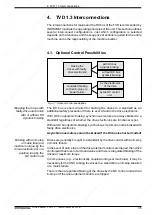
Fig. 3.10: Connecting the additional bleeder module TBM 1.2
APTBM
TVD 1.3
TBM 1.2
10 mm , twisted
max 1 m
L-
L+
EB
L-
L+
X7
twisted
7
8
24 V 0 V
24 V 0 V
X 16
X 15
min. 1 mm
2
2
24 V - route leads and
EB leads separately
24 V-blower power
current consumption
140 mA
X3
EB


