54
• DOK-POWER*-TVD*1.3****-ANW1-EN-E1,44 • 02.97
Remedy
Remedy
Remedy
6. Troubleshooting
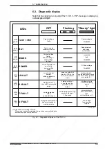
6.3. Definition of the displays
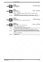
Fig. 6.2: Diagnostics displays on the TVD 1.3
+24 V/
±
15 V
Display green:
(Operating status)
Signal voltages are OK.
DATVD1.3
LED red
LED green
+24V /
±
15V
I-FAULT
H1
POWER
H2
H3
H4
MAINS
Bb1
B
A
P-FAULT
T-FAULT
U-FAULT
A
H2
H1
B
+24V /
±
15V
Bb1
A
H2
H1
B
+24 V /
±
15 V
Bb1
Remedy
Remedy
A
H1
B
H2
+24 V /
±
15 V
Bb1
A
H1
B
H2
+24 V /
±
15 V
Bb1
+24 V /
±
15 V / +5 V
Display dark:
(Fault - not stored)
Signal voltage faulty.
Cause 1: Missing or faulty mains input voltage for electronic supply.
Check mains fuse in the control panel.
Cause 2: Maximum load of the signal voltages exceeded.
1. Disconnect wire-ribbon connection (X1) to the drive modules
and check voltages at X3.
2. Disconnect signal voltages and check for short-circuits
(+ 24 V: max. 2 A;
±
15 V: respect. max. 100 mA).
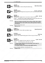
Bb1
Display green:
(Operating status)
No faults in supply modules or drives.
Bb1
Display dark:
(Fault - stored)
Fault in supply module or drive.
Cause 1: Fault in supply module
Check the remaining diagnostics displays of the supply module.
Cause 2: Drive module fault
Check diagnostics display of the drive module.
Cause 3: Fault in the signal voltage bus connection
Check bus cable at X1 and end connector of the bus connection
should be checked whether properly in place.

