6.
Prepare for microprocessor installation:
a.
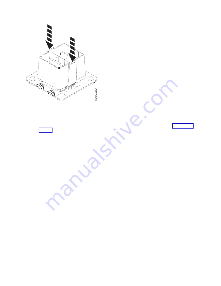
Grasping the sides of the tool and microprocessor, carefully lift it slightly out of the
microprocessor tray. Then turn it over so that the microprocessor side is up.
b.
Ensure that all four jaws (A) are firmly grabbing the microprocessor, as shown in Figure 41 on
page 78.
Note:
If one of the jaws is not firmly grabbing the microprocessor, press down on the corner of
the microprocessor closest to the jaw until it locks into place. Do not touch any part of the
microprocessor other than the corners.
Figure 40. Locking the microprocessor into the tool
Chapter 6. Installing and removing components
77
Summary of Contents for Flex System p270 Compute Node
Page 1: ...Power Systems IBM Flex System p270 Compute Node Installation and Service Guide IBM ...
Page 2: ......
Page 3: ...Power Systems IBM Flex System p270 Compute Node Installation and Service Guide IBM ...
Page 38: ...26 Power Systems IBM Flex System p270 Compute Node Installation and Service Guide ...
Page 40: ...28 Power Systems IBM Flex System p270 Compute Node Installation and Service Guide ...
Page 110: ...98 Power Systems IBM Flex System p270 Compute Node Installation and Service Guide ...
Page 498: ...486 Power Systems IBM Flex System p270 Compute Node Installation and Service Guide ...
Page 509: ...Appendix Notices 497 ...
Page 510: ...IBM Printed in USA ...


