


Figure 73
Figure 74
122587
Before executing assembly, check the Rocker Arm driving
rods: these shall not be deformed; the spherical ends in
contact with the Rocker Arm adjustment screw and with the
tappet (arrows) shall not present evidence of seizure or wear:
in case of detection proceed replacing them.
The rods driving the suction and exhaust valves are identical
and therefore interchangeable.
75703
-
Insert the tappet driving rods and the Rocker Arm unit.
Before using the fixing screws again, measure them twice
as indicated in the picture, checking D1 and D2
diameters:
if
D1 - D2 < 0,1 mm the screw can be utilised again;
if
D1 - D2 > 0,1 mm the screw must be replaced;
Figure 75
75806
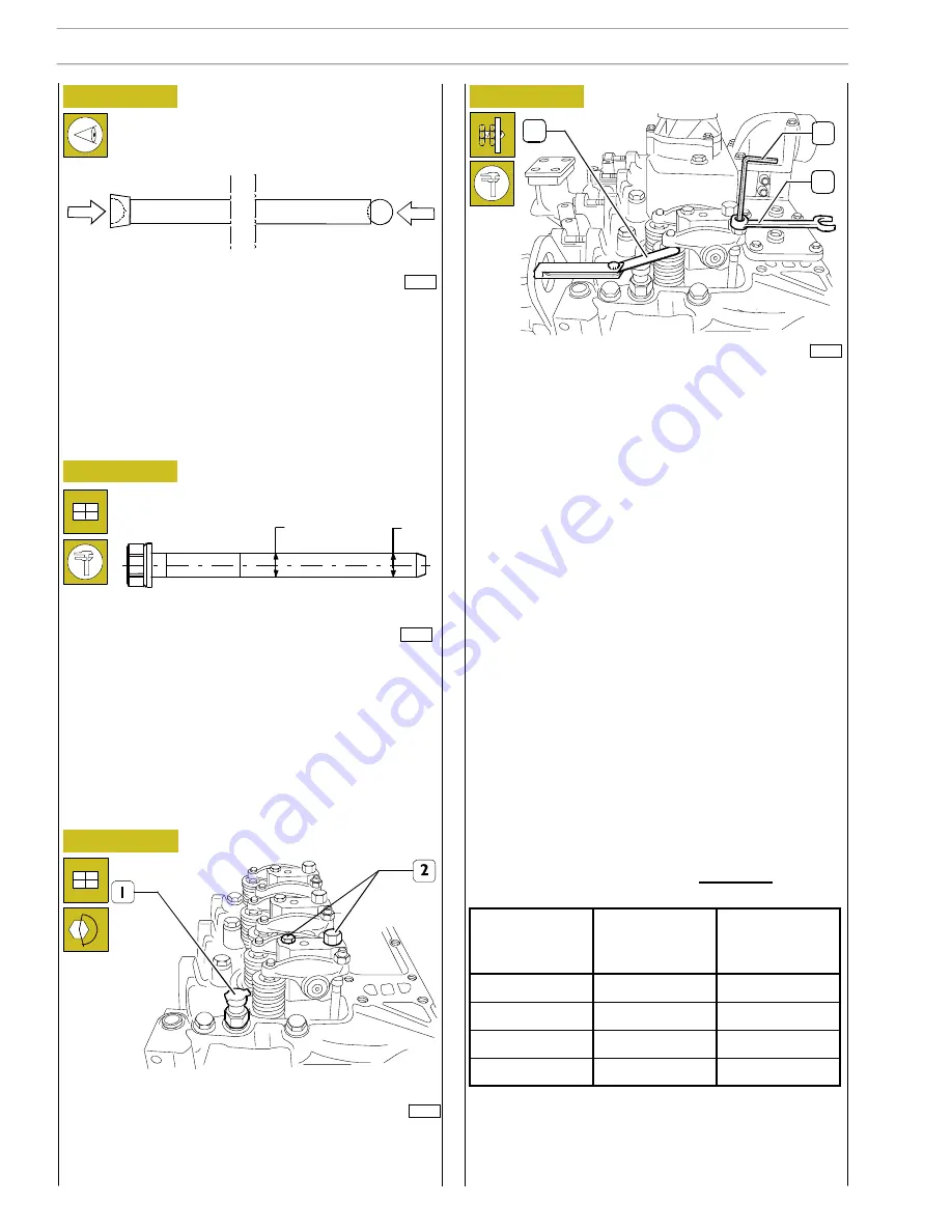
On TIER 3 engines, due to the additional lobe for the
INTERNAL E.G.R., it is not possible to use the valve clearance
adjustment procedure that requires adjusting the clearance
of all the valves by positioning the crankshaft 2 times only.
Each cylinder must be checked by taking it to the T.D.C. (top
dead centre) at the end of compression and adjusting the
clearance of both valves on the cylinder in question.
Remove the rocker covers of the cylinder; remove the
injector and place the tool 99395097(see Figure 98) to set
the cylinder top dead centre position (end-of-compression
phase). Pre-load the gauge.
The searched condition is obtained by rotating the engine
shaft properly until you find the maximum value on the
comparator and then checking that the intake and exhaust
valves are both closed.
Adjust the slack between rocker arms and valves using socket
wrench (1), point wrench (3) and feeler gauge (2).
Correct slack is:
- suction valves 0.25
0.05 mm
- exhaust valves 0.50
0.05 mm.
IGNITION SEQUENCE: 1 - 3 - 4 - 2
D1
D2
2
1
3
Figure 76
125114
-
Tighten the screws (2) to the prescribed couple and
assemble water temperature sensor (1).
28
SECTION 3 - AGRICULTURAL APPLICATION
F4GE N SERIES
Base - February 2009
Print P2D32N010 E
Engine shaft
starting and
rotation
Bilance
valves
cylinder n°
Adjust intake and
exhaust valves
clearance cylinder
n°
1° al PMS
1
1
180°
3
3
180°
4
4
180°
2
2
Summary of Contents for F4GE9454J*J604
Page 3: ...F4GE N Series Part 1 F4GE N SERIES 1 F4GE N SERIES Print P2D32N010 E Base Febraury 2009...
Page 4: ...2 F4GE N SERIES Base Febraury 2009 Print P2D32N010 E...
Page 6: ...2 INTRODUCTION F4GE N SERIES Base Febraury 2009 Print P2D32N010 E...
Page 16: ...2 F4GE N SERIES Base February 2009 Print P2D32N010 E...
Page 18: ...4 F4GE N SERIES Base February 2009 Print P2D32N010 E...
Page 20: ...2 SECTION 1 GENERAL SPECIFICATIONS F4GE N SERIES Base February 2009 Print P2D32N010 E...
Page 28: ...2 SECTION 2 FUEL F4GE N SERIES Base February 2009 Print P2D32N010 E...
Page 34: ...8 SECTION 2 FUEL F4GE N SERIES Base February 2009 Print P2D32N010 E...
Page 40: ...6 SECTION 3 AGRICULTURAL APPLICATION F4GE N SERIES Base February 2009 Print P2D32N010 E...
Page 42: ...8 SECTION 3 AGRICULTURAL APPLICATION F4GE N SERIES Base February 2009 Print P2D32N010 E...
Page 74: ...40 SECTION 3 AGRICULTURAL APPLICATION F4GE N SERIES Base February 2009 Print P2D32N010 E...
Page 76: ...42 SECTION 3 AGRICULTURAL APPLICATION F4GE N SERIES Base February 2009 Print P2D32N010 E...
Page 80: ...46 SECTION 3 AGRICULTURAL APPLICATION F4GE N SERIES Base February 2009 Print P2D32N010 E...
Page 82: ...48 SECTION 3 AGRICULTURAL APPLICATION F4GE N SERIES Base February 2009 Print P2D32N010 E...
Page 90: ...56 SECTION 3 AGRICULTURAL APPLICATION F4GE N SERIES Base February 2009 Print P2D32N010 E...
Page 132: ...2 SECTION 5 TOOLS F4GE N SERIES Base February 2009 Print P2D32N010 E...
Page 138: ...8 SECTION 5 TOOLS F4GE N SERIES Base February 2009 Print P2D32N010 E...
Page 140: ...2 APPENDIX F4GE N SERIES Base February 2009 Print P2D32N010 E...


