178
Inspection, care and maintenance
Mechanical adjustments
7
Switch-off / securing mechanisms
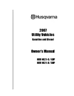
Pic. 41
Chassis without loading bridge
1
Chassis
2
Loading bridge ball mounting
3
Switch-off function
The switch-off function
(Pic. 41 /3) must be checked
and readjusted as required if the
loading bridge was
independently installed by the
superstructure manufacturer.
Maintenance and repair work on
the switch-off and securing
mechanisms may only be
carried out by trained and
qualified personnel!
Pic. 42
Lateral tilting position
1
Loading bridge ball mounting
2
Securing cord
3
Elastic cable
The loading bridge must be
secured with a maintenance
brace before carrying out
maintenance / repair work.
Tip the loading bridge to the right / left
and to the rear.
Check that the lifting of the loading
bridge is stopped by the lift limitation
valve.
The securing cord (Pic. 42 /2) may not
be used to limit the stroke of the
loading bridge.
Check that the cylinder does not push
against the top ball mounting
(Pic. 42 /1) of the loading bridge.
Ensure that the securing cables are
guided and cannot get tangled, e.g. by
using an expander cable (Pic. 42 /3).
W - 032
1
3
2
W - 033
1
2
3
Summary of Contents for 10000 Series
Page 6: ...Contents 4 ...
Page 11: ...9 1 Safety ...
Page 28: ...Personal protective equipment rules prohibitions 26 Safety 1 ...
Page 29: ...27 2 General information ...
Page 39: ...37 3 Operation ...
Page 61: ...59 4 Operating the chassis ...
Page 102: ...100 Operating the chassis Warning tables optional 4 ...
Page 103: ...101 5 Operating the body ...
Page 144: ...5 Roll up tarpaulin optional 142 Operating the body ...
Page 145: ...143 6 Electrical system ...
Page 158: ...6 TIM iTAP 156 Electrical system ...
Page 159: ...157 7 Inspection care and maintenance ...
Page 218: ...7 Disposal 216 Inspection care and maintenance ...
Page 219: ...217 8 Troubleshooting ...