


Installing a DC power supply
Installing a DC power supply
WARNING:
WARNING: To reduce the risk of electric shock, be sure that the cable grounding kit is properly
installed and connected to a suitable protective earth terminal before connecting the power
source to the frame.
Two lugs ship in the kit with the -48V DC power supply. The two-hole lug specification is as follows:
Width – 0.41 in (10.41 mm)
Bolt hole size – 0.20 in (5.08 mm)
Hole spacing – 0.63 in (16.00 mm)
Prerequisites
Prerequisites
Be sure the -48V DC power cables are installed. For more information, see the HPE Synergy 12000 Frame -48V DC Power Cable
Installation Instructions.
Be sure that a ground connection to the HPE Synergy 12000 Frame has been properly installed. See Installing the DC power
grounding kit or the document that ships with the kit.
Gather the following tools:
Torx T-25 screwdriver
Crimper
Procedure
Procedure
1. Place the power supply on a flat, level surface.
2. Open the input connector on the new power supply by lifting the input connector cover.
3. Crimp a two-hole lug onto the -48V DC cable.
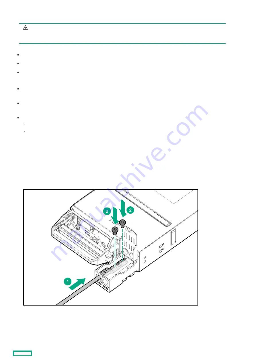
4. Insert the two-hole lug through the aperture labeled "-48V" on the power supply input connector.
5. Secure the two-hole lug to the -48V DC input connector terminal with two screws.
6. Using a torque-controlled T-25 screwdriver, tighten both screws to 15 lb-in of torque.
7. Crimp a two-hole lug onto the return cable.
8. Insert the two-hole lug through the aperture labeled "RTN" on the power supply input connector.
9. Secure the two-hole lug to the RTN input connector terminal with two screws.
Installing a DC power supply
113
Summary of Contents for HPE Synergy 12000 Frame
Page 7: ...Planning the installation Planning the installation 7 ...
Page 23: ...Component and LED identification Component and LED identification 23 ...
Page 25: ...Information pull tabs 25 ...
Page 29: ...Figure 5 Optional horizontal half shelf Device bay partitions 29 ...
Page 33: ...Appliance bay numbering Appliance bay numbering 33 ...
Page 67: ...Installation Installation 67 ...
Page 85: ...Installing a device bay shelf 85 ...
Page 98: ...Installing drives in the storage module 98 ...
Page 101: ...Installing interconnect modules 101 ...
Page 119: ...Installing the DC power grounding kit with bracket 119 ...
Page 122: ...Configuring HPE Synergy Configuring HPE Synergy 122 ...
Page 124: ...HPE Synergy Console connections HPE Synergy Console connections 124 ...
Page 149: ...Troubleshooting Troubleshooting 149 ...
Page 157: ...Shift Insert Paste selected text Keyboard shortcut Action HPE Synergy Console icons 157 ...
Page 175: ...Support and other resources Support and other resources 175 ...


