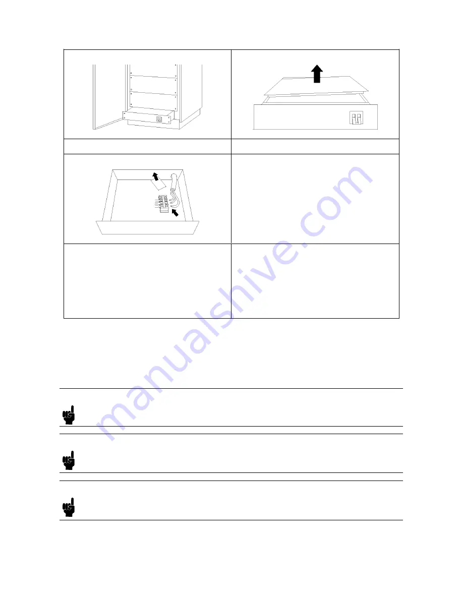
5.
Remov
e
the
PDU
from
the
cabinet.
6.
Remov
e
the
top
co
v
er
of
the
PDU.
7.
P
ass
the
main
p o
w
er
cable
through
the
rear
op ening
of
the
PDU.
8.
Remov
e
the
clear
plastic
co
v
er
from
the
p o
w
er
cable
terminal
unit.
9.
Connect
the
p o
w
er
cables
to
the
terminals
of
the
p o
w
er
cable
terminal
unit.
10.
Reinstall
the
clear
plastic
co
v
er
on
the
p o
w
er
cable
terminal
unit.
11.
F
asten
the
cable
clamp
securely
.
12.
Reinstall
the
top
co
v
er
of
the
PDU.
13.
Reinstall
the
PDU
in
the
cabinet.
14.
Connect
the
c
hassis
ground
cable
of
the
PDU
to
the
cabinet
frame.
15.
Reinstall
the
rear
plate.
16.
Connect
the
p o
w
er
cables
of
the
instrumen
ts
and
the
hour
meter
to
the
PDU.
17.
Close
the
rear
do or.
Installing
P
o
w
er
Cables
for
Each
Instrument
P
o
w
er
cables
for
eac
h
rac
k
moun
ted
instrumen
t
are
installed
b efore
the
HP
4062
system
is
shipp ed
from
the
factory
.
Before
y
ou
turn
the
HP
4062
on,
ho
w
ev
er,
make
sure
that
all
p o
w
er
plugs
are
completely
inserted
in
to
the
outlets
of
the
PDU.
Note
Before
y
ou
turn
the
HP
4062
on,
make
sure
that
the
line
v
oltage
selector
switch
of
eac
h
instrumen
t
is
set
correctly
.
Refer
to
the
Op
er
ation
Manual
of
eac
h
instrumen
t
for
instructions
on
ho
w
to
set
these
switches.
Note
According
to
the
system
conguration,
y
ou
may
not
b e
able
to
supply
electric
p o
w
er
from
the
PDU
to
other
instrumen
ts,
con
trollers,
and
p eripherals.
See
the
Pr
e-instal
lation
Manual
on
the
p o
w
er
requiremen
ts.
Note
If
the
line
v
oltage
in
y
our
area
is
b et
w
een
220
V
ac
and
240
V
ac,
connect
eac
h
instrumen
t,
con
troller,
or
p eripheral
to
the
PDU
via
the
p o
w
er
cable
(HP
part
n
um
b er
8120-1763)
when
y
ou
w
an
t
to
supply
the
p o
w
er
from
the
PDU.
System
Installation
4-7
Summary of Contents for HP 4062F
Page 13: ...B 2 Printer Con guration Softkey Map B 3 Contents 7 ...
Page 18: ......
Page 34: ......
Page 46: ......
Page 60: ...Figure 4 5 Installing the HP 4280A 4 14 System Installation ...
Page 63: ...Figure 4 7 Attaching Rack Flanges for HP 4284A System Installation 4 17 ...
Page 95: ...Figure 5 1 Installation Flowchart for HP 4062UX F System Software Software Installation 5 3 ...
Page 105: ...1140 HF7 PG41 1150 HF8 PG42 1160 HF9 PG51 1170 HF10 PG52 Software Installation 5 13 ...
Page 112: ......
Page 135: ...Figure 6 27 An Example Page of View Result Printer System Verification 6 23 ...
Page 159: ...Figure 6 49 An Example Page of View Result Printer System Verification 6 47 ...
Page 160: ......
Page 162: ......
Page 168: ......
Page 173: ...Error when reading from or writing to a le Installation Problems You May Encounter C 5 ...
Page 174: ......


