32
HRXDS Series DVR User Guide
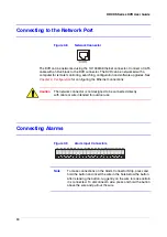
Connect the device to the COM and NC (Normally Closed) connectors or COM and
NO (Normally Open) connectors. NC/NO is a relay output which sinks 2 A @ 125 VAC,
1 A @ 250 VAC, 1 A @ 30 VDC (NC) and 5 A @ 125 VAC, 2 A @ 250 VAC,
3 A @ 30VDC (NO).
ARI (Alarm Reset In)
Figure 2-12
Alarm Reset Input Connectors
An external signal to the Alarm Reset In can be used to reset both the Alarm Out signal
and the DVR's internal buzzer. Mechanical or electrical switches can be wired to the ARI
(Alarm Reset In) and GND (Ground) connectors. The threshold voltage is below 0.3V
and should be stable at least 0.5 seconds to be detected. Connect the wires to the ARI
(Alarm Reset In) and GND (Ground) connectors.
Connecting to the Ultra Wide SCSI Port
Figure 2-13
SCSI Port
A SCSI port is provided to connect external storage devices for recording or archiving
video. Connect the external SCSI hard disk drive (RAID) cable to the high-density 68-pin
female UltraWide SCSI port. The length of SCSI cable should not exceed 5 feet (1.5
meters). You can connect up to 8 UltraWide SCSI devices with SCSI IDs set from 0 to
15 except for 7, which is assigned as the Host ID.
Note
The SCSI bus must be terminated, otherwise the DVR will not
operate properly.
Note
When using low speed SCSI devices, the recording speed might
decrease.
Summary of Contents for HRXDS16
Page 8: ...8 ...
Page 12: ...Contents 12 ...
Page 18: ...Tables 18 ...
Page 24: ...24 HRXDS Series DVR User Guide ...
Page 102: ...102 HRXDS Series DVR User Guide ...
Page 138: ...138 HRXDS Series DVR User Guide ...
Page 152: ...152 HRXDS Series DVR User Guide ...
Page 154: ...154 HRXDS Series DVR User Guide ...
Page 156: ...156 HRXDS Series DVR User Guide ...
Page 160: ...160 HRXDS Series DVR User Guide ...
Page 162: ...162 HRXDS Series DVR User Guide ...
Page 164: ...164 HRXDS Series DVR User Guide ...
Page 171: ......


