Document 800-04559
Rev D
31
11/09
Installation
AI 1 to 16 (Alarm-In)
You can use external devices to signal the DVR to react to events. Mechanical switches
can be used to open/close the circuit between Alarm In and GND to trigger an event.
You can also use electrical switches to apply electric voltage to Alarm In (0V and 5V) to
trigger an alarm with common ground: 2.4~5 VDC for 0.5 seconds is required to trigger
an alarm on NC (Normally Closed) Alarm In. For NO (Normally Open) Alarm In, below
0.3 VDC for at least 0.5 seconds is required to trigger an alarm. See
for configuring alarm input.
GND (Ground)
Note
All the connectors marked GND are common.
Connect the ground side of the Alarm input and/or alarm output to the GND connector.
AO 2 to 16 (Alarm-Out)
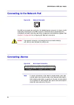
Figure 2-10
Alarm Output Connectors
The DVR can activate external devices such as buzzers or lights. Connect the device to
the AO (Alarm-Out) and GND (Ground) connectors. AO is an active low open collector
output which sinks 30mA@12VDC. See
for configuring alarm
output.
NC/NO (Relay Alarm Output)
Figure 2-11
Relay Alarm Output Connectors
N
C
C
O
M
N
O
N C
C O M N O
Summary of Contents for HRXDS16
Page 8: ...8 ...
Page 12: ...Contents 12 ...
Page 18: ...Tables 18 ...
Page 24: ...24 HRXDS Series DVR User Guide ...
Page 102: ...102 HRXDS Series DVR User Guide ...
Page 138: ...138 HRXDS Series DVR User Guide ...
Page 152: ...152 HRXDS Series DVR User Guide ...
Page 154: ...154 HRXDS Series DVR User Guide ...
Page 156: ...156 HRXDS Series DVR User Guide ...
Page 160: ...160 HRXDS Series DVR User Guide ...
Page 162: ...162 HRXDS Series DVR User Guide ...
Page 164: ...164 HRXDS Series DVR User Guide ...
Page 171: ......


