background image

Tables

18

Summary of Contents for HRXDS16

Page 1: ...Document 800 04559 Rev D 11 09 User Guide HRXDS8 HRXDS16 8 16 Channel Models Digital Video Recorder ...

Page 2: ...2 Revisions Issue Date Revisions A 07 09 New document B 08 09 Corrected document p n Minor changes throughout C 08 09 Changed two figures in Configuration chapter D 11 09 Updated back cover ...

Page 3: ...expressly approved by the party responsible for compliance could void the user s authority to operate the equipment This Class A digital apparatus complies with Canadian ICES 003 Cet appareil numérique de la Classe A est conforme à la norme NMB 003 du Canada CE Complliance This equipment has been tested in accordance with the following directives 2006 95 EC The Low Voltage Directive 2004 108 EC Th...

Page 4: ... disposed with other household wastes at the end of its working life To prevent possible harm to the environment or human health from uncontrolled waste disposal please separate this from other types of wastes and recycle it responsibly to promote the sustainable reuse of material resources Household users should contact either the retailer where they purchased this product or their local governme...

Page 5: ...rious injury to a child or adult and serious damage to the equipment Wall or shelf mounting should follow the manufacturer s instructions and should use a mounting kit approved by the manufacturer This equipment and cart combination should be moved with care Quick stops excessive force and uneven surfaces may cause the equipment and cart combination to overturn 7 Power Sources This equipment shoul...

Page 6: ...he operating instructions as an improper adjustment of other controls may result in damage and will often require extensive work by a qualified technician to restore the equipment to its normal operation If the equipment has been dropped or the cabinet damaged When the equipment exhibits a distinct change in performance this indicates a need for service 14 Replacement Parts When replacement parts ...

Page 7: ...ack should be such that the amount of airflow required for safe operation of the equipment is not compromised 21 Mechanical Loading Mounting of the equipment in the rack should be such that a hazardous condition is not caused by uneven mechanical loading 22 Circuit Overloading Consideration should be given to connection of the equipment to supply circuit and the effect that overloading of circuits...

Page 8: ...8 ...

Page 9: ...t SVHS Out 28 Spot Out 28 VGA Port 29 Connecting to the RS485 Port 29 Connecting to the Network Port 30 Connecting Alarms 30 AI 1 to 16 Alarm In 31 GND Ground 31 AO 2 to 16 Alarm Out 31 NC NO Relay Alarm Output 31 ARI Alarm Reset In 32 Connecting to the Ultra Wide SCSI Port 32 Connecting to the RS232 Port 33 Connecting to the USB Ports 33 Factory Reset 34 Connecting Audio 35 Connecting the Power C...

Page 10: ...t Screen 98 Event Status Screen 101 4 Operation 103 Turning on the Power 103 Live Monitoring 104 Active Cameo Mode 105 PIP Mode 105 Zoom Mode 105 PTZ Mode 105 Image Adjustment 107 Event Monitoring 108 Covert Camera 108 Spot Monitoring 109 Using a Mouse 110 Recording Video 112 Recording Audio 113 Playing Recorded Video 113 Searching Video 116 Go to 117 Calendar Search 118 Record Table Search 119 Ev...

Page 11: ...3 System Requirements 143 Launching WebGuard 143 Troubleshooting 145 Web Monitoring Mode 146 Web Search Mode 149 Appendix E Time Overlap 153 Appendix F Solutions 155 Appendix G Connector Pin Outs 157 I O Connector Pin Outs 157 RS485 Connector Pin Outs 158 Appendix H Map of Screens 159 Appendix I System Log Notices 161 Appendix J Error Code Notices 163 Appendix K Specifications 165 Index 167 ...

Page 12: ...Contents 12 ...

Page 13: ...1 Figure 2 12 Alarm Reset Input Connectors 32 Figure 2 13 SCSI Port 32 Figure 2 14 RS232 Port 33 Figure 2 15 USB Ports 33 Figure 2 16 Factory Reset Switch 34 Figure 2 17 Audio In and Out Connectors 35 Figure 2 18 Power Cord Connector 35 Figure 3 1 16 Channel DVR Front Panel Controls 37 Figure 3 2 Remote Control 39 Figure 3 3 Login Screen 43 Figure 3 4 Setup Screen 43 Figure 3 5 Virtual Keyboard 44...

Page 14: ...ication Callback Setup Screen 66 Figure 3 34 Device Menu 67 Figure 3 35 Camera Setup Screen 67 Figure 3 36 Camera PTZ Setup Screen 69 Figure 3 37 PTZ Device List 69 Figure 3 38 Port Setup Window 70 Figure 3 39 Audio Setup Screen 70 Figure 3 40 Alarm Out Settings Screen 71 Figure 3 41 Alarm Out Schedule Screen 71 Figure 3 42 OSD Display Screen 72 Figure 3 43 OSD Margin Screen 74 Figure 3 44 Main Mo...

Page 15: ...e 3 74 Text In Actions 2 Screen 98 Figure 3 75 System Event Health Check Screen 99 Figure 3 76 Check Recording Screen 99 Figure 3 77 Storage Screen 100 Figure 3 78 Event Status Screen 101 Figure 4 1 PTZ Select Camera Menu 106 Figure 4 2 PTZ Preset Screens 106 Figure 4 3 PTZ Menu 107 Figure 4 4 PTZ Toolbar Controls 107 Figure 4 5 Spot Monitor Menu 109 Figure 4 6 Sequence Menu 110 Figure 4 7 Mouse M...

Page 16: ...creen 131 Figure B 1 Text In Search Example 1 Screen 136 Figure B 2 Text In Search Example 2 Screen 137 Figure C 1 ClipPlayer Screen 140 Figure D 1 WebGuard Login Screen 144 Figure D 2 WebWatch Screen 146 Figure D 3 WebSearch Screen 149 Figure G 1 I O Connector Pin Outs 157 ...

Page 17: ...les Table 2 1 16 Channel DVR Real Panel Connector Descriptions 26 Table 3 1 16 Channel DVR Front Panel Descriptions 38 Table 3 2 Infrared Remote Control Descriptions 39 Table D 1 System Requirements for WebGuard 143 Table F 1 Troubleshooting 155 ...

Page 18: ...Tables 18 ...

Page 19: ... an overview of the front panel controls and LCD displays and provides instructions for configuring the DVR Chapter 4 Operation covers live monitoring recording video and audio playing recorded video and searching for video Appendix A USB Hard Disk Drive Preparation shows how to prepare the USB hard disk drive for computers using Microsoft Windows Vista operating system Appendix B Text In Search E...

Page 20: ...pendix I System Log Notices lists all of the System Log notices Appendix J Error Code Notices lists the system upgrade and clip copy Error Code notices Appendix K Specifications lists the DVR specifications ...

Page 21: ...e with Color NTSC or PAL and B W CCIR and EIA 170 Video Sources Auto Detection for NTSC and PAL Multiple Monitor Connectors 1 BNC Video Out 1 SVHS 4 Spot 1 VGA Pentaplex Functionality Monitoring Recording Playback Archiving and Transmission at the same time Multiple Search Engines Date Time Calendar Event Records up to 240 200 Images per Second NTSC PAL Loop Through Video Connectors Continuous Rec...

Page 22: ...ogy also allows you to view recorded video while the DVR continues recording video Digitally recorded video has several advantages over analog video recorded on tape There is no need to adjust tracking You can freeze frames fast forward fast reverse slow forward and slow reverse without image streaking or tearing Digital video can be indexed by time or events and you can instantly view video after...

Page 23: ...licity the illustrations and descriptions in this manual refer to the 16 camera model Figure 1 1 Typical DVR Installation Up to 16 Cameras RGB Monitor Monitor NTSC or PAL Up to 4 Monitors NTSC or PAL Up to 16 Sensors VGA Out Video Out Spot Outs Up to 4 Audio Inputs Audio Output IR Remote Control Up to 3 USB Device Mouse Support External SCSI Hard Disk Drive Internal DVD RW Digital Video Recorder N...

Page 24: ...24 HRXDS Series DVR User Guide ...

Page 25: ...sted on the order form and packing slip The HRXDS Series DVR packing box should include Digital Video Recorder Power cord User Guide this document Multilingual User Guide RASplus CD ROM RASplus User Guide Multilingual RASplus Software CD and User Guide RASplus CD ROM DVRNS Server Software and User Guide RASplus CD ROM Rack mount Kit Assembly screws and guide rails for adding Hard Disk Drive Screws...

Page 26: ... but you cannot mix them For example you cannot use a PAL camera and an NTSC monitor N C C O M N O 17 1 2 3 4 5 6 7 8 9 10 11 12 13 14 15 16 Table 2 1 16 Channel DVR Real Panel Connector Descriptions Location Description Location Description 1 Video In 2 Video Loop Through 3 Video Out 4 SVHS Out 5 Spot Out 6 RS485 Port 7 Network Port 8 Alarm Reset In 9 SCSI Port 10 Alarm Out 11 VGA Port 12 RS232C ...

Page 27: ...ideo In connectors Connecting the Loop Through Video Figure 2 3 Video Loop Through Connectors If you would like to connect your video source to another device you can use the Loop BNC connectors Note The Loop BNC connectors are auto terminated Do NOT connect a cable to the Loop BNC unless it is connected to a terminated device because it will cause poor quality video ...

Page 28: ...onnect the main monitor to either the Video Out or SVHS Out connector Note If your main monitor has an SVHS input Honeywell recommends that you use it for better quality video display Spot Out Figure 2 5 Spot Out Connectors Connect up to four spot monitors to the SPOT 1 SPOT 2 SPOT 3 and SPOT 4 connectors as needed ...

Page 29: ...dual monitors for simultaneous operation Connecting to the RS485 Port Figure 2 7 RS485 Connector The DVR can be controlled remotely by an external device or control system such as a control keyboard using RS485 half duplex serial communications signals The RS485 connector can also be used to control PTZ pan tilt zoom cameras Connect RX TX and RX TX of the control system to the and respectively of ...

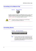
Page 30: ... Chapter 3 Configuration for configuring the Ethernet connections Caution The network connector is not designed to be connected directly with cable or wire intended for outdoor use Connecting Alarms Figure 2 9 Alarm Input Connectors Note To make connections on the Alarm Connector Strip press and hold the button and insert the wire in the hole below the button After releasing the button tug gently ...

Page 31: ...m In below 0 3 VDC for at least 0 5 seconds is required to trigger an alarm See Chapter 3 Configuration for configuring alarm input GND Ground Note All the connectors marked GND are common Connect the ground side of the Alarm input and or alarm output to the GND connector AO 2 to 16 Alarm Out Figure 2 10 Alarm Output Connectors The DVR can activate external devices such as buzzers or lights Connec...

Page 32: ...age is below 0 3V and should be stable at least 0 5 seconds to be detected Connect the wires to the ARI Alarm Reset In and GND Ground connectors Connecting to the Ultra Wide SCSI Port Figure 2 13 SCSI Port A SCSI port is provided to connect external storage devices for recording or archiving video Connect the external SCSI hard disk drive RAID cable to the high density 68 pin female UltraWide SCSI...

Page 33: ...e is operating the DVR system might not operate normally Connecting to the RS232 Port Figure 2 14 RS232 Port An RS232 port is provided to connect a remote control keyboard Connecting to the USB Ports Figure 2 15 USB Ports Three USB ports are provided to connect external hard disk CD RW or flash drives for video clip copying or system upgrades One USB port is on the rear panel and the other two are...

Page 34: ... This switch will only be used on the rare occasions that you want to return all the settings to the original factory settings Caution When using the Factory Reset you will lose any settings you have saved To reset the unit you will need a straightened paperclip 1 Turn the DVR off 2 Turn it on again 3 While the DVR is initializing the front panel LEDs will blink When any of the Camera 1 to 8 LEDs ...

Page 35: ...sources to Audio In 1 Audio In 2 Audio In 3 and Audio In 4 as needed using RCA jacks Connect Audio Out to your amplifier Note The DVR does not have amplified audio output so you will need a speaker with an amplifier The DVR does not have a pre amplifier for audio input so the audio input should be from an amplified source not directly from a microphone Connecting the Power Cord Figure 2 18 Power C...

Page 36: ...y UPS to minimize the potential of damage to the DVR from undesired power related hazards Connect the UPS between the DVR and the AC voltage supply WARNING ROUTE POWER CORDS SO THAT THEY ARE NOT A TRIPPING HAZARD MAKE CERTAIN THE POWER CORD WILL NOT BE PINCHED OR ABRADED BY FURNITURE DO NOT INSTALL POWER CORDS UNDER RUGS OR CARPET THE POWER CORD HAS A GROUNDING PIN IF YOUR POWER OUTLET DOES NOT HA...

Page 37: ...tup Using the menu screens to set up your network configure devices and program recording and event settings Note Your DVR should be completely installed before proceeding See Chapter 2 Installation Front Panel Controls Figure 3 1 16 Channel DVR Front Panel Controls 1 2 3 4 5 6 7 8 9 10 11 12 13 14 15 16 17 18 19 20 21 22 23 ...

Page 38: ...t of arrow buttons Make certain that nothing blocks the sensor or the remote control will not function properly Note You can also use a USB mouse not supplied to navigate through the screens and menus much like you would on a computer Table 3 1 16 Channel DVR Front Panel Descriptions Location Description Location Description 1 Camera buttons 2 SEARCH button 3 PANIC button 4 PLAY PAUSE button 5 Shu...

Page 39: ... s t e m I D 1 2 3 4 1 2 3 4 5 6 7 8 9 10 11 12 13 14 15 16 17 18 19 20 21 22 Table 3 2 Infrared Remote Control Descriptions Location Description Location Description 1 System ID button 2 SPOT buttons 3 DISPLAY button 4 SEQUENCE button 5 Camera buttons 6 Focus Near Far 7 MENU button 8 PANIC button 9 STOP button 10 RW Rewind button 11 FF Fast Forward button 12 ALARM button 13 FREEZE button 14 Set M...

Page 40: ...ockwise to play video backward Playback speed varies with the amount the ring is turned The playback speeds are and x0 5 and When you release the ring it snaps back to the center position and the video pauses Jog Dial When in the playback mode you can play video forward image by image by turning the Jog Dial clockwise and backward image by image by turning the Jog Dial counterclockwise When in the...

Page 41: ... display a single camera or all cameras sequentially The infrared remote control allows you to go directly to the individual Spot Monitor menus PTZ Button Press PTZ to enter the PTZ Pan Tilt Zoom mode which allows you to control properly configured cameras FREEZE Button Press FREEZE to freeze the current live screen In the Search mode clip copying can be done instantly by pressing and holding the ...

Page 42: ...the System ID of two or more DVRs is set to 0 those DVRs will react to the infrared remote control at the same time Turning On the Power Connecting the power cord to the DVR turns on the unit The unit takes approximately 60 seconds to initialize Initial Unit Setup Before using your DVR for the first time you will want to establish the initial settings This includes items such as time and date disp...

Page 43: ... the system setting up a password is strongly recommended Logging In Using a Mouse You can use a mouse not supplied to access the Login screen in addition to using the front panel buttons or the infrared remote control Click the right mouse button to display the Login screen To enter a password click the button and the virtual keyboard displays See instructions below for using the virtual keyboard...

Page 44: ... the next position 3 Press to toggle between the upper and lower case keyboards Press to backspace an entered character Press to delete entered characters You can use up to 31 characters including spaces in your title 4 To create special characters use and a capital letter For example J for NL New Line M for CR Carriage Return Special characters are commonly used by text input devices and will be ...

Page 45: ...e RS485 network It is possible to have multiple DVRs with System ID 0 that are in the same area as long as they are not part of an RS485 network If this is the case all will be controlled at the same time when using the infrared remote control 4 Highlight the box beside Language then press A drop down menu displays the available languages Highlight the desired language then press 5 The box beside ...

Page 46: ...The USB device must be FAT16 or FAT32 format Importing and Exporting DVR Settings You can import saved DVR settings or export the current DVR settings To import saved DVR settings 1 Connect the USB device containing the setup file dat to the DVR 2 Highlight Setup Import then press 3 Select the desired setup file then press Import to import the selected settings and change the DVR settings accordin...

Page 47: ...t be FAT16 or FAT32 format Displaying the System Log To display the system log 1 Highlight Show System Log then press to display the System Log screen Figure 3 10 System Log Screen The System Log screen lists system activities up to 5 000 from the latest that have occurred along with the time and date The icon displays in the last column for system activities of the remote site 2 You can scroll th...

Page 48: ...creen you can highlight Save then press to save the changes and exit the screen If you do not wish to save the changes highlight Cancel then press to exit the screen Date Time Setup To access the Date Time Setup screen 1 On the main Setup screen see Figure 3 4 highlight Date Time then press The Date Time Setup screen appears Figure 3 11 Date Time Setup Screen 2 Highlight the first box beside Date ...

Page 49: ...ilable time formats then press to save your selected format Note The clock will not start running until you have highlighted Save and pressed the button 6 Highlight the box beside Time Zone then press Select your time zone from the list then press 7 Highlight Use Daylight Saving Time then press Pressing toggles between On and Off Setting a Holiday Schedule To set a holiday schedule 1 On the Date T...

Page 50: ...Highlight the box beside Time Server then press A virtual keyboard appears that you can use to enter the IP address or domain name of the time server Note You can use the domain name instead of the IP address if you already set up the DNS server when setting up the LAN 4 Highlight the box beside Interval then press Set the time interval for synchronization from 30 minutes to 1 day at various time ...

Page 51: ...rmat a device for recording or archiving Figure 3 15 Device Format Screen Column Description Type Displays the storage device Capacity Provides the capacity of the storage device Format Displays whether the device is used for recording Record or archiving Archive Not Using indicates the device is not used for either recording or archiving Not formatted indicates the device is not formatted indicat...

Page 52: ...isk drives even though they are not used for either recording or archiving The Information column displays whether the device is being used In Use or not Other indicates the device has been used for another DVR Viewing Storage Device Information 1 Highlight the box in the Information column for the desired storage device then press You will be able to check the time information about recorded data...

Page 53: ...ation on setting up disk mirroring Viewing Storage Status 1 On the Storage screen highlight the Status tab The Storage Status screen displays Figure 3 17 Storage Status Screen Column Description Type Displays the type of storage device Disk Bad Displays the percentage of bad sectors Not formatted indicates the device is not formatted Temperature Displays the temperature of the storage device S M A...

Page 54: ...displays the authorized groups and users 1 On the main Setup screen see Figure 3 4 highlight User then press 2 Now you can add and delete groups and users When adding a group you can assign authority levels to the group as a whole Figure 3 18 User Setup Screen 3 The column is used to collapse and expand user groups A or in this column indicates the item is a Group Name An in front of the Group Nam...

Page 55: ... PC running RAS log the user out of the system first and then delete the user 7 To add a Group highlight the Group box then press A virtual keyboard appears allowing you to enter the Group name You can use up to 15 characters including spaces in the group name 8 Now you can assign authority levels to the group Highlight the Authority box then press to toggle between all authority levels being turn...

Page 56: ...l system or a PC running RAS PTZ Control The user can control the PTZ camera on a local system or a PC running RAS Alarm Out Control The user can reset the DVR s outputs including the internal buzzer during an alarm by pressing the ALARM button on a local system or alarm out control button on a PC running RAS Covert Camera View The user can view video from cameras set as Covert while in the Live M...

Page 57: ...es highlight Save then press Select Cancel to exit the screen without saving the changes Shutdown Screen To shut the system down 1 On the main Setup screen see Figure 3 4 highlight Shutdown then press 2 You are prompted to confirm whether or not you want to shut the system down 3 After selecting Shutdown then pressing a screen appears telling you when it is safe to disconnect power Figure 3 21 Shu...

Page 58: ...twork setup screen displays see Figure 3 24 You will be able to change the Network LAN DVRNS and WebGuard settings Figure 3 24 Network Setup Screen 2 Highlight the first box beside Transfer Speed Press the Up and Down arrow buttons to set the Transfer Speed from 50 Kbps to 100 Mbps 3 Highlight the second box beside Transfer Speed You can select the unit of measure for the transfer speed between bp...

Page 59: ...dio channel that sends audio to the remote site Choosing Select From RAS will send audio of the channel selected from RAS Note Depending on network conditions audio might be interrupted or out of synchronization during transmission LAN Setup 1 On the Network setup screen see Figure 3 24 highlight the LAN tab to display the LAN setup screen Figure 3 25 LAN Manual Setup Screen 2 Highlight the box be...

Page 60: ... then press The Port Number Setup screen appears Figure 3 26 Port Number Setup Screen Note You will need to get the appropriate Port Numbers for each RAS and WebGuard related program Admin Callback Watch Search and Audio from your network administrator 7 Change the numbers by highlighting them and using the Up and Down arrow buttons to increase or decrease the number The factory default Port setti...

Page 61: ...n changing the port settings you must change the port settings on the PC running RAS or WebGuard as well Refer to the RAS manual for details LAN DHCP Setup Select DHCP from the Type drop down list then highlight Save to read the current DVR IP address configured by DHCP Dynamic Host Configuration Protocol network Figure 3 27 LAN DHCP Setup Screen LAN ADSL with PPPoE Setup 1 Select ADSL with PPPoE ...

Page 62: ...e the virtual keyboard to enter the password for ADSL connection Note Entering the ID and Password and highlighting OK reads the current IP address of the DVR configured by the ADSL network Note If the DVR is configured for DHCP or an ADSL network the DVR IP address might change whenever the unit is turned on DVRNS Setup 1 On the Network setup screen see Figure 3 24 highlight the DVRNS tab The DVR...

Page 63: ...then press Use the virtual keyboard to enter the IP address or domain name of the DVRNS server Note You will need to get the IP Address or domain name of the DVRNS Server from your network administrator Note You can use the domain name instead of IP address if you already set up the DNS Server when setting up the LAN 4 Highlight the box beside Port then press Set the port number of the DVRNS serve...

Page 64: ...the DVR on the DVRNS server Proper DVRNS settings display the help desk information of the DVRNS server in the box beside Help Desk WebGuard Setup 1 On the Network setup screen see Figure 3 24 highlight the WebGuard tab The WebGuard screen displays Figure 3 30 WebGuard Setup Screen 2 Highlight Use WebGuard Service then press to toggle between On and Off See Appendix D WebGuard for detailed descrip...

Page 65: ...yboard appears that you can use to enter the IP address or domain name of the SMTP server Note You will need to get the IP Address or domain name of the SMTP Server from your network administrator Note You can use the domain name instead of IP address if you already set up the DNS Server when setting up the LAN 4 Highlight the box beside Port then press Use the arrow buttons to enter the SMTP Serv...

Page 66: ...n Callback 1 On the Notification screen see Figure 3 31 highlight the Callback tab The Callback screen displays Figure 3 33 Notification Callback Setup Screen 2 Highlight LAN then press to toggle between On and Off When LAN is turned On you can change the IP addresses 3 Highlight the IP Address box that you want to change then press Use the arrow buttons to enter the IP address of the computer you...

Page 67: ... number on and off Change the camera title Determine which cameras display on the monitors Adjust the video resolution 1 In the Device menu highlight Camera then press The Camera Setup screen appears Figure 3 35 Camera Setup Screen 2 You can turn the camera number On or Off and you can change the Title of each camera using the virtual keyboard You can also determine which cameras display on the mo...

Page 68: ...No 1 cameras 1 to 8 and No 2 cameras 9 to 16 for the 16 channel model and No 1 cameras 1 to 4 and No 2 cameras 5 to 8 for the 8 channel model The maximum recording speed for all cameras in each camera group will be limited to 120 ips when set to Standard resolution 60 ips when set to High resolution 30 ips when set to Very High resolution When set to High resolution for all cameras within the same...

Page 69: ...a from the list then press You must connect the camera to the RS232 or RS485 connector on the back of the DVR following the camera manufacturer s instructions Figure 3 37 PTZ Device List 4 To assign IDs to each camera highlight the appropriate box under the ID heading then press Change the number by highlighting it and using the Up and Down arrow buttons to increase and decrease the number The PTZ...

Page 70: ...creen 2 The DVR can record up to four audio inputs Highlight the box beside the input then press A list of cameras appears and you can select which camera you want associated with that audio input 3 Highlight Enable Audio Out then press This toggles between enabling and disabling audio out 4 To save your Audio changes highlight Save then press Select Cancel to exit the screen without saving the ch...

Page 71: ...r the Type heading to set the alarm output for NO or NC normally open or normally closed 4 Highlight the box beside Dwell Time then press to set the dwell time from 5 seconds to 15 minutes of the alarm output Alarm Out Schedule 1 On the Alarm Out screen highlight the Schedule tab to open the Schedule screen Figure 3 41 Alarm Out Schedule Screen 2 You can add and edit alarm output schedules on this...

Page 72: ...hat the alarm schedule will be active The choices are Sun Mon Tue Wed Thu Fri Sat M F Hol and All Range Allows you to set the time that the alarm schedule will be active in 15 minute increments from 00 00 to 24 00 Mode Allows you to set how the alarm reacts during the scheduled time On means the Alarm Out is active during the scheduled time Event means the Alarm Out is only active when there is an...

Page 73: ...8 channel DVR Free Space The DVR is in the Recycle mode and the percentage of available storage space displays when the DVR is not in the Recycle mode Archive The DVR is archiving recorded data Mirror Disks are mirroring Date Time Current date and time The current date and time information displays User Name Current user name The name of the current user logged in displays Camera No Camera number ...

Page 74: ...u can adjust the display dwell time for each camera displayed on the main monitor 3 Highlight the box beside Mode then press You can select between Full Sequence and Cameo Sequence 4 Press the SEQUENCE button to have the DVR sequence between cameras The DVR can sequence cameras in two modes Full and Cameo In Full mode the DVR sequences through the cameras and displays them full screen In Cameo mod...

Page 75: ... 4x4 display mode of the 16 channel and 3x3 mode of the 8 channel DVR 6 To adjust the display dwell time highlight the box beside Interval then press You can select dwell intervals ranging from 1 second to 1 minute 7 Highlight Event Monitoring On then press Press to toggle between On and Off When it is On the DVR displays the camera associated with the event when an event occurs Spot Monitor 1 On ...

Page 76: ... PTZ control networking or text input the remote keyboard cannot be configured 3 Highlight Setup and select the correct Baud Rate Parity Data Bits and Stop Bits for the device you are connecting to the DVR 4 Highlight the box beside Remote Control Product and select the device from the list 5 To save your Remote Control settings highlight Save then press Select Cancel to exit the screen without sa...

Page 77: ...ore details 3 Highlight the box beside Paper Size and select the paper size 4 Highlight the box beside Quality and select the printing quality Note Selecting Quality may not be supported depending on the printer model Recording Settings Your DVR offers a variety of flexible recording modes You can set it up to record all the time or to only record events It can be set up to continue recording afte...

Page 78: ...nd Right arrow buttons to adjust the length of time recorded data will be kept from 1 to 99 days The DVR automatically deletes video recorded earlier than the user defined period under three conditions at midnight whenever the system reboots or whenever the user changes the Auto Deletion settings Select Never to disable the Auto Deletion function 5 Highlight the slide bar beside Limit Time Lapse R...

Page 79: ...set the duration of panic recording from 5 minutes to 1 hour Panic recording stops automatically after the preset duration unless panic was toggled Off by pressing the PANIC button in advance of the panic recording duration time out Select No Limit if you want to stop panic recording manually 8 Highlight Panic Recording ips then press to set the images per second for Panic recording from 1 00 to 3...

Page 80: ...ll event and action statuses 4 Highlight the then press to add a schedule item Note The higher the number under the No heading the higher its priority 5 Highlight the box under the Day heading then press to change the days that the scheduled recording will take place Choose from Sun Mon Tue Wed Thu Fri Sat M F Hol and All 6 Highlight the box under the Range heading then press to change the time ra...

Page 81: ... the Settings heading then press to define the recording settings You can set the ips and Quality of the recording for any modes you set up in the Mode column If you do not set the ips and Quality in the Settings column the DVR will follow the default settings See below for details 10 Highlight the box under the heading then press to delete the recording settings You are prompted to confirm that y...

Page 82: ...ality can be selectable from Very High High Standard and Low 3 You can set the amount of time to record prior to the event by adjusting the Dwell You can set the Dwell from 5 seconds to 30 minutes The longer the dwell set the fewer maximum ips can be set Note When the DVR is in the Time or Time Event mode it ignores the pre event settings and follows the time settings 4 To save your changes highli...

Page 83: ...wish to enter specific times and dates in From and To toggle the check marks Off and then enter the time and date 5 Highlight Recycle then press to toggle between On and Off When Recycle is On and the storage device is full the newest archived video data will overwrite the oldest archived data When Recycle is Off the DVR will stop archiving video data until more space is made available 6 To save y...

Page 84: ...n press A virtual keyboard appears allowing you to enter a title name 4 Each input can be set as NO normally open or NC normally closed 5 You can set up the DVR to start panic recording whenever it senses an input on one of its alarm input connectors Highlight the box beside Panic Record then press A list of Alarm Inputs appears and you can select which alarm input you want associated with panic r...

Page 85: ...e desired box under the Alarm Out heading then press A list of Alarm Outputs and Beep appears Select the Alarm Output connectors that you would like to activate whenever the DVR detects an input on the associated alarm input You can also set the DVR s internal buzzer to sound Note For the Alarm Out action the alarm output and beep you select should be set to the Event mode in the Alarm Out setup s...

Page 86: ...t PTZ cameras to move to whenever the DVR detects an input on the associated alarm input 14 Highlight the desired box under the Spot Monitor column then press A list of SPOT monitors and cameras appears Each SPOT monitor can be associated with a camera The DVR will display the associated camera on the SPOT monitor whenever it detects an input on the associated alarm input 15 To save your Alarm In ...

Page 87: ...t be activated to trigger a motion alarm Highlight the box under the Min Blocks column then press to adjust the minimum number of detection blocks for Daytime and Nighttime independently Smaller numbers provide greater sensitivity because fewer detection blocks must be activated Figure 3 61 Motion Detection Min Blocks Screen 5 Turning Zone View On will allow you to observe how the DVR is reacting ...

Page 88: ...the Up and Down arrow buttons and individual blocks within the block groups are selected or cleared using the camera buttons 7 Press to display the menu screen Figure 3 63 Motion Detection Zone Menu The menu on the setup screen has the following functions Menu Item Function Select Activates highlighted blocks to detect motion Clear Deactivates highlighted blocks so they will not detect motion Reve...

Page 89: ... box beside Daytime then press Use the Up and Down arrow buttons to set the Daytime range The DVR will consider the remaining time range as the Nighttime Figure 3 64 Daytime Setup Screen 11 Highlight the Actions 1 and Actions 2 tabs to display the Motion Detection Actions 1 and Actions 2 screens Setting Motion Detection Actions The DVR can be set to react to motion detection differently for each c...

Page 90: ...er the Alarm Out column then press A list of Alarm Outputs appears You can associate as many Alarm Outs with that camera as you wish When the DVR detects motion on the selected camera s input it triggers output signals on all the associated Alarm Out connectors You can also have the DVR s internal buzzer sound if motion is detected on the selected camera Note For the Alarm Out action the alarm out...

Page 91: ...PTZ cameras to move to whenever the DVR detects motion on the selected camera s input 6 Highlight the desired box under the Spot Monitor column then press A list of SPOT monitors and cameras appears Each SPOT monitor can be associated with a camera The DVR will display the associated camera on the SPOT monitor whenever it detects motions on the selected camera 7 To save your Motion Detection chang...

Page 92: ...deo Loss Actions 1 Screen Setting Video Loss Actions 1 The DVR can be set to react to video loss differently for each camera Each camera can be Associated with another camera Trigger an Alarm Out connector Sound the DVR s internal buzzer Notify a number of different devices Move PTZ cameras to preset positions Display a camera on a SPOT monitor 2 Highlight the box under the Record column then pres...

Page 93: ... beep you select should be set to the Event mode in the Alarm Out setup screen Schedule tab 4 Highlight the box under the Notify column then press You can toggle the entire list On and Off by highlighting Notification then press You can toggle the individual items On and Off by highlighting that item then press Highlight OK then press to accept your changes Note For the Notify action the notify it...

Page 94: ...ghlight Text In then press The Text In setup screen appears Figure 3 70 Text In Settings Screen 2 The DVR can be set to react to text input from devices such as ATMs Automated Teller Machines and POS Point of Sale that is cash registers This screen allows you to configure the DVR for each text in device 3 Highlight the box under the Setup column then press Selecting the Setup heading changes all t...

Page 95: ... Serial 1 8 Note If you have set the Port as None you will not be able to make any changes to the screen Note When using the USB to serial text in device do NOT remove the USB cable from the port while the system is running 5 Highlight Setup then press Use the ATM or POS manufacturer s recommended settings when configuring the RS232 RS485 or USB Serial ports 6 Highlight the box beside Text In Prod...

Page 96: ...ord from 0 to 10 12 Highlight the box beside Line Delimiter then press Use the virtual keyboard to enter the character s that the device uses to indicate the end of a line Special characters can be created using and a capital letter for example J for NL New Line M for CR Carriage Return Refer to the device manufacturer s documentation for Line Delimiter character s 13 Highlight the box beside Igno...

Page 97: ...should be set to the Event or Time Event recording mode in the Record Schedule setup screen 19 Highlight the box beside Alarm Out then press A list of Alarm Outputs appears You can associate as many Alarm Outs with the Text Input as you wish When the DVR detects text input it triggers output signals on all the associated Alarm Out connectors You can also have the DVR s internal buzzer sound if tex...

Page 98: ...era where you want PTZ cameras to move to when the DVR detects text input 22 Highlight the box beside Spot Monitor then press A list of SPOT monitors and cameras appears Each SPOT monitor can be associated with a camera The DVR will display the associated camera on the SPOT monitor whenever it detects an input on the selected text in device 23 To save your Text In changes highlight Save then press...

Page 99: ...edule On then press to toggle On and Off When set to On you can select the day time range and interval that you want the DVR to run self diagnostics on the recorder The Interval can be selectable from 1 min to 7 days or Never The box allows you to delete a check recording schedule Note The higher the number under the No heading the higher its priority Figure 3 76 Check Recording Screen 5 Highlight...

Page 100: ...ut signals on all the associated Alarm Out connectors You can also have the DVR s internal buzzer sound if an event is detected Note Alarm Out action cannot be set to System and Panic Record events 8 Highlight the Notify box beside the desired event System Panic Record Check Recording Check Alarm In Disk Almost Full Disk Full Disk Bad Disk Temperature or Disk S M A R T then press To toggle the ent...

Page 101: ...k drive status See Storage Screen section for more details Event status Is highlighted Alarm In Motion Video Loss Text In When each event is detected based on the settings you made in the Alarm In Motion Detection and Text In setup screen on the Event menu Check Alarm In Check Recording When each event is detected based on the settings you made in the System Event setup screen on the Event menu Pa...

Page 102: ...102 HRXDS Series DVR User Guide ...

Page 103: ...laying back video However you have much greater control over recording and playing back video You can establish recording schedules based on time of day and day of the week The DVR allows you to search through the recorded video using much more sophisticated tools than those available with VCRs Additional DVR features that are not available with VCRs are remote control and viewing and recording vi...

Page 104: ...NCE button to display the cameras sequentially When in one of the multi view formats pressing this button will cause the DVR to go through predefined screen layouts Full Sequence Or the bottom right screen will display live cameras sequentially Cameo Sequence To exit Sequence mode select another display mode or press the SEQUENCE button again When in one of the multi view formats press the Left or...

Page 105: ... Dial clockwise or counterclockwise Zoom Mode To enlarge an area of the video press the ZOOM button For a few seconds after pressing the ZOOM button a PIP displays Inside the PIP a rectangle shows the area that is enlarged You can move the rectangle around using the arrow buttons While in the Zoom mode you can enlarge the area more by pressing The Zoom mode options are 2x 3x and 4x Exit the Zoom m...

Page 106: ...an save camera position settings as presets so that you can go directly to desired views a After you have the camera at the desired settings press the button and the PTZ Preset dialog box will appear b Select the number you want to assign to the preset and press c Use the virtual keyboard to enter the preset name Press the button to load the PTZ preset and the Preset View dialog box will appear Se...

Page 107: ... the screen Change the toolbar location by clicking the empty space on the left side of the toolbar and drag it to where you want it located on the screen Use the arrow buttons on the toolbar to pan or tilt the camera in the direction you want The other controls on the toolbar perform as described below Image Adjustment Note It is important that cameras and monitors are correctly installed and adj...

Page 108: ... If five to nine cameras are associated with the event the DVR will display the cameras on a 3x3 screen If 10 or more cameras are associated with the event the DVR will display the cameras on a 4x4 screen Event monitoring lasts for the dwell time set for event recording After the dwell time has elapsed the monitor returns to the previous screen unless another event has occurred If you want to retu...

Page 109: ...ess the SPOT button on the front panel or remote control and select one of four Spot Monitors 2 Then select the camera to be displayed on the Spot Monitor Figure 4 5 Spot Monitor Menu 3 If you want to display more than one camera on a Spot Monitor you can display them sequentially In the Spot Monitor selection mode press the SEQUENCE button on the front panel or remote control or select Sequence O...

Page 110: ...f the DVR functions The following operations are supported when using a mouse during live monitoring When in one of the multi view formats for example PIP 2x2 3x3 or 4x4 click the mouse button on a camera image to switch that camera to full screen Click the mouse button again to return to the previous multi view format When in one of the multi view formats scrolling the mouse wheel up and down ope...

Page 111: ...ck Previous Group or Next Group is the same as pressing the Left or Right buttons on the front panel which moves to the previous or next page 4 Select Edit Group for the active cameo function a Select Edit Group and choose a camera that you want to change display position for example Camera A Mouse Menu Options Description Freeze PTZ Spot Monitor Is the same as pressing the FREEZE PTZ and SPOT but...

Page 112: ...ndard CIF High 2 CIF or Very High 4 CIF The factory default resolution is Standard When set to Standard the DVR has a maximum recording speed of 240 ips When set to High the DVR has a maximum recording speed of 120 ips When set to Very High the DVR has a maximum recording speed of 60 ips Press the PANIC button to start panic recording of all cameras Press PANIC again to stop panic recording If you...

Page 113: ...ack video of all cameras The DVR maintains the same display format as it does in the live mode except for the PIP format You can also change the screen layout in the same way as you do in the live mode 2 Select a camera number under Triplex to enter the Triplex mode and play back video of the selected camera When in the single screen display format the camera currently displayed on the screen will...

Page 114: ...ed Pressing the button again toggles the playback speed between and The screen displays and respectively Entering Fast Backward Playback mode from Live Monitoring mode can be password protected FF Fast Forward Button Press the FF button plays video forward at high speed Pressing the button again toggles the playback speed between and The screen displays and respectively Entering Fast Playback mode...

Page 115: ...es Jog Dial The Jog Dial only functions when playback video has been paused Turn the jog dial clockwise to play video forward image by image Turn the jog dial counterclockwise to play video backward image by image You can use a mouse for convenient playback control Position the mouse pointer at the bottom of the search screen and the following search toolbar will display Figure 4 10 Mouse Playback...

Page 116: ... using a calendar See Calendar Search for more details Record Table Search Searches using a recording table See Record Table Search for more details Event Log Search Selects video from the event log See Event Log Search for more details Text In Search Searches text input strings See Text In Search for more details Motion Search Searches motion events See Motion Search for more details Clip Copy Cl...

Page 117: ...ference of 1 60 second 1 50 second for PAL between odd and even fields because it is composed of 60 interlaced fields per second 50 fields for PAL When recording video with Very High 4 CIF resolution video is made up of frame units combining two fields one odd field and one even field This can cause horizontal scan lines or flashes in areas with motion because of the time difference between the tw...

Page 118: ...h recorded video by using the arrow buttons After you have highlighted a day press to select it 2 A time bar displays at the bottom of the calendar Hours in which video was recorded will be highlighted with blue Use the Up and Down arrow buttons to highlight the time bar After the time bar is highlighted select the time by using the Left and Right arrow buttons Note The time bar is in one hour seg...

Page 119: ...Record Table Search Figure 4 15 Record Table Search Screens 1 Recording information about video images currently displayed on the screen displays on the recording status bar A white vertical line indicates the current search position To search specific video move the vertical line by using the Left or Right arrow buttons on the front panel or by clicking the mouse on the desired segment If the DVR...

Page 120: ...Note If the DVR has images recorded in more than one recording mode in the same time range the recording status bar displays recording information in the following priority order Panic Pre Event Event Time The color of the bar indicates different recording modes Red for Panic Yellow for Pre Event Purple for Event and Blue for Time 4 Select located at the bottom to displays the Search menu 5 Select...

Page 121: ...rity to display the Event Log Search screen however the event video will not be played unless a user with Search authority logs into the system 2 Press the button to extract the event video and display the first image of the event Press the PLAY PAUSE button to start playing the event video segment Press SEARCH to return to live monitoring Note If no recorded image displays on the current screen p...

Page 122: ...s date and time have been reset it is possible for the DVR to have more than one overlapping start and stop time When set to On you will be asked to select one of the overlapping start and stop time When set to Off the DVR will display search results from all start times to all stop times 4 Highlight the box beside Alarm In then press You can select the alarm inputs that you want to include in you...

Page 123: ...e Event Log Search screen Select Cancel to exit the screen without saving the changes Text In Search Figure 4 18 Text In Search Screen 1 The DVR maintains a log of each time there is Text Input The Text In Search screen displays this list Use the arrow buttons to highlight the event for which you would like to see video 2 Press to extract the video associated with the Text Input and display the fi...

Page 124: ...the box beside To then press to toggle between On and Off When set to Off you can enter a specific Date and Time When set to On the search will be from the last recorded image 3 Highlight the Channel then press Select the text in devices that you want to search for text input 4 Highlight the Text Input Device box then press Select your Text Input Device from the list 5 Highlighting the then press ...

Page 125: ... 1 You can select the Motion Search from the Search menu see Figure 4 11 while the DVR displays the camera full screen The Motion Search screen displays a list of motion events Use the arrow buttons to highlight the event for which you would like to see video then press to display the video associated with the selected event on the small search screen 2 Highlight Close then press to extract the vi...

Page 126: ...e in which you want to search for motion Note Defining the area of the image in which you want to search for motion is nearly identical to setting up the DVR for Motion Detection See Motion Detection Screen on page 86 for detailed instructions on setting up the detection blocks Note When setting the Museum Search Zone the zone should be placed inside of the border line of the target object If the ...

Page 127: ...o set the starting point of the video to be clip copied and the icon displays at the bottom left corner of the screen Pressing the FREEZE button again to set the ending point of the video to be clip copied by displaying the Clip Copy screen 3 Press and hold the FREEZE button for more than two seconds while in the Search mode or Live Monitoring mode to initiate the One Touch Clip Copy function The ...

Page 128: ...age and USB CD RW Caution The USB device for clip copy must be FAT 16 or FAT32 format Note While copying video clips on the CD RW or DVD RW the recording speed might decrease Note While copying video clips on the CD RW or DVD RW the DVR will stop archiving video data until clip copy is finished Note When the error message Firmware update of the optical drive is required displays update the firmwar...

Page 129: ...ting Close When selecting Close Clip Copy continues and a confirmation screen displays when complete Note Only 4 7 GB DVD media is available To clip copy video on DVD media using remaining space the size of previously recorded data on the DVD media should be less than 4GB Note Select Full Erase when erasing recorded data on DVD media otherwise the media will not operate properly when rewritten Not...

Page 130: ...ps You will need to power down the DVR and restart it to get rid of the error message After the file system of the USB hard disk drive has been corrupted this error message cannot be dismissed Even after restarting the DVR it may automatically restart while preparing to clip copy You must recover the file system using the recovery program or you must reformat the hard disk drive Print Screen You c...

Page 131: ...e destination disk from a list of internal hard disk drives 3 Highlight the boxes under Source and Dest then press to select the source disk and the destination disk for the Mirror Note Please note the following The source disk can be designated only from devices formatted for recording A device formatted for archiving cannot be used for disk mirroring The manufacturer model and capacity of the so...

Page 132: ...ta on the two disks at the same time will start Note Resynchronization will pause while searching video 5 After disk mirroring starts you can cancel it by highlighting Stop then press Select Stop to display a confirmation screen asking you to confirm whether or not you want to stop mirroring for the selected disk Note After disk mirroring stopped the destination disk will be set to Not Used If res...

Page 133: ...rd disk drive is partitioned or has data it will show up in My Computer as a hard disk drive icon Check the file system by right clicking on the icon and checking under Properties General File System If the file system is NOT FAT32 format format the USB hard disk drive using the FAT32 format 4 If the USB hard disk drive is not partitioned a Go to Control Panel Administrative Tools and launch Compu...

Page 134: ...User Guide Note The partition size should be less than 32 GB because of Microsoft limitations 6 After formatting is complete the USB hard disk drive will be added to My Computer 7 Connect the USB hard disk drive to the DVR ...

Page 135: ...h Qty and 40th amount characters including spaces from the left In this case you can enter 17 28 and 40 in each Column box For example if you want to search for Coke with a Qty Quantity of more than 1 and Hotdog with an amount totaling over 8 the following search condition can be set 123456789012345678901234567890123456789012345678901234567890 Item Unit price Qty amount Coke 2 20 1 s 2 20 Fanta 2 ...

Page 136: ...d 40th amount characters including spaces from the left but the value of amount category is located on a different line from Item In this case you can enter 17 28 and 40 in each Column box and enter 1 in the Line box for the next line 123456789012345678901234567890123456789012345678901234567890 Item Unit price Qty amount Coke 2 20 1 s 2 20 Fanta 2 20 1 s 2 20 Hotdog 3 50 3 s 10 50 Pepsi 1 95 1 s 1...

Page 137: ...t 800 04559 Rev D 137 11 09 For example if you want to search for Coke with a Qty Quantity of more than 1 and Hotdog with an amount totaling over 8 the following search condition can be set Figure B 2 Text In Search Example 2 Screen ...

Page 138: ...138 HRXDS Series DVR User Guide ...

Page 139: ...m the DVR and connect it to your PC If you used a recordable CD insert the CD in your computer s CD drive Double click the target clip file to start the ClipPlayer program Note Honeywell suggests that the computer used for the ClipPlayer program has at least an 800MHz Pentium III If your CPU is slower than this video clips recorded at maximum speed with very high image quality will be played back ...

Page 140: ...at DirectX version 9 0 or higher has been installed To check the version of DirectX 1 Click Start Run 2 In the Open field type dxdiag then click OK or press the Enter key The DirectX Diagnostic Tool dialog box will display 3 Move to the Display tab and make sure DirectDraw Acceleration is set to Enabled 4 Test the DirectDraw by selecting the DirectDraw Test button 5 Please check the driver version...

Page 141: ...ime type size and resolution informatiion about the image Image Processing Controls brightness blur and sharpness of playback images Single Screen Layout and Pause Mode Only Play Speed Control Changes the playback speed Play or fast forward backward playback speed FF RW Drawing Mode Selects the draw mode level If you are not sure about the best draw mode level for your system try each level until ...

Page 142: ...ution Full Screen might not display properly when selected If this happens press ESC on your PC to return to the normal screen mode Slider Bar Moves through the video clip Mouse Cursor Place and click on an image to display that image full frame Controls Function Options Function Save as Image Saves the current image as a bitmap or JPEG file Save as Image Actual Size Saves the current video frame ...

Page 143: ...s for using the WebGuard program are Launching WebGuard 1 Start Internet Explorer on your local PC You can run the WebGuard program by entering the following information in the address field Table D 1 System Requirements for WebGuard Component Minimum Requirement Operating System Microsoft Windows 2000 Microsoft Windows XP or Microsoft Windows Vista CPU Intel Pentium III Celeron 600 MHz or faster ...

Page 144: ...h modes and enter the appropriate port number of the program 3 Enter the ID and PASSWORD then clickg LOGIN to log on using the selected mode 4 Select Save ID to save the ID you entered Note The port numbers for WEBWATCH WEBSEARCH and Audio should be the same port numbers used for Remote Watch Remote Search and Remote Audio set during Network setup http IP address port number The DVR IP address and...

Page 145: ...n Internet Explorer Permission Levels When running WebGuard in the Microsoft Windows Vista operating system it is recommended to start Internet Explorer with elevated administrator permissions Click the right mouse button on the Internet Explorer icon and select the Run as administrator option from the context menu Otherwise some functions of the WebGuard might be limited to use Screen Display Scr...

Page 146: ...fter running the Command Prompt with elevated administrator permissions 2 Restart your computer to apply the changes Web Monitoring Mode WebWatch is a remote web monitoring program that allows you to monitor live video transmitted in real time from the remote DVR Figure D 2 WebWatch Screen ...

Page 147: ... format to select the desired display mode When changing the screen format the selected camera on the current screen will be located in the first cell of the new layout 6 Camera button 1 to 6 Selects the camera to be viewed 7 Adjust the brightnss contrast saturation and hue of the monitoring image 8 Control the pan tilt and zoom of the camera from a remote site 9 Control alarm out devices at the r...

Page 148: ... a camera on the screen Displays the text menu WebGuard Controls Function Options Function Change Camera Title Changes the camera name Enable Audio Enables audio communication with the remote site When the audio control panel displays click to send audio to the connected remote site and click the button again to stop sending audio Click to monitor live audio from the connected remote site through ...

Page 149: ...de WebSearch is a remote web search program that allows you to search recorded video on the remote DVR Note The remote site connection in the Web Search mode will automatically be disconnected if there is no activity for 30 minutes Figure D 3 WebSearch Screen ...

Page 150: ...isplay mode 8 Enters the time lapse search mode which allows you to search for recorded data by time and then play back images found within the time parameters The Timetable window located at the bottom displays the time information for the image of the date selected on the calendar If more than one video stream in the same time range you can select the video stream you want to search Clicking a s...

Page 151: ... time range select the video segment you want to search from the SEGMENT menu at the top right corner on the timetable 16 Right click a camera on screen Displays the text menu screen WebSearch Controls Function Options Function Change Camera Title Changes the camera name Enable Audio Plaus audio while playing back recorded video that has recorded audio Single Screen mode only Aspect Ratio Changes ...

Page 152: ...152 HRXDS Series DVR User Guide ...

Page 153: ...apping video streams by selecting a specific time or time range If you want to search recorded video at four o clock during the overlapping time range using a search menu such as Go to the Date Time select the segment you want to search If you want to search recorded video from four to five o clock during the overlapping time range using a search menu such as Event Log Search Text In Search or Mot...

Page 154: ...154 HRXDS Series DVR User Guide ...

Page 155: ...tions Confirm that the camera has power Check camera lens settings Live video very bright If a cable is attached to the Loop connector make certain it is connected to a properly terminated device DVR stops recording If hard disk drive is full you will either need to delete video or set the DVR to the Overwrite Mode The icon displays however the DVR is not recording When the DVR is in the Pre Event...

Page 156: ...156 HRXDS Series DVR User Guide ...

Page 157: ...for the I O and RS485 connectors I O Connector Pin Outs Figure G 1 I O Connector Pin Outs N C C O M N O AI 1 to 16 Alarm Inputs 1 to 16 GND Chassis Ground 6 connectors NC Relay Alarm Output Normally Closed COM Relay Common NO Relay Alarm Output Normally Open A0 2 to 16 Alarm Outputs 2 to 16 ARI Alarm Rest In ...

Page 158: ...158 HRXDS Series DVR User Guide RS485 Connector Pin Outs Master Unit Slave Unit To TX To TX To RX To RX ...

Page 159: ...System Network Devices Record Event Information Date Time Storage User System Shutdown Log Out Alarm In Motion Detection Video Loss Text In System Event Event Status Record Schedule Pre Event Archive Camera Audio Alarm Out Display Remote Control Printer Network Notification ...

Page 160: ...160 HRXDS Series DVR User Guide ...

Page 161: ... Time Sync Search End Time Sync Fail Clip Copy Begin Disk Bad Clip Copy End Login Clip Copy Cancel Logout Clip Copy Fail Setup Begin Clip Copy User Setup End Clip Copy From Remote Setup Change Clip Copy To Remote Setup Fail Clip Copy Duration of Video Setup Imported Clip Copy Camera Setup Imported Failure Callback Fail Setup Exported Print Begin Setup Export Failure Print End Setup Export Cancel P...

Page 162: ...162 HRXDS Series DVR User Guide ...

Page 163: ... 105 Invalid package 10 Database has been changed 106 ODD firmware upgrade failed 11 Appending failed 300 Remote connection failed 12 Bad sector 301 Remote network error 13 No executable file 302 Remote upgrade is not authorized 14 Opening executable file failed 303 Saving remote package failed 15 Writing executable file failed 304 Remote uprade is cancelled by the user 16 Creating image failed 40...

Page 164: ...164 HRXDS Series DVR User Guide ...

Page 165: ...1 A 30 VDC NC 5 A 125 VAC 2 A 250 VAC 3 A 30 VDC NO Alarm Reset Input 1 TTL Internal Buzzer 80 dB at 10 cm Network Connectivity 10 100 Mbps Ethernet RJ45 Audio Input RCA Input 4 Line In Audio Output RCA Output 1 Line Out IR Port 1 Remote Control CONNECTORS Video Input Composite 8 or 16 BNC Video Loop Composite 8 or 16 BNC Auto Terminating Monitor Output Composite 1 BNC SVHS 1 YC VGA 1 VGA SPOT Com...

Page 166: ...16 9 in x 3 5 in x 15 9 in 430 mm x 88 mm x 405 mm Unit Weight 22 5 lbs 10 2 kg Shipping Weight 27 6 lbs 12 5 kg Operating Temperature 41 F to 104 F 5 C to 40 C Operating Humidity 0 to 90 Power 100 to 240 VAC 2 A 60 50 Hz Power Consumption Max 85W Approvals FCC UL CB CE CAUTION Risk of explosion if battery is replaced by an incorrect type Dispose of used batteries according to the instructions Thi...

Page 167: ...n 140 connectors alarm input 30 alarm output 31 alarm rest in 32 audio in out 35 GND 31 loop through 27 network port 30 power cord 35 rear panel locations 26 relay alarm output 31 RS232 33 RS485 29 SCSI port 32 spot monitor 28 SVSH out 28 USB ports 33 VGA port 29 video input 27 video out 28 controls front panel 37 38 remote control 39 42 D date time setup screen 48 daytime setup screen 89 default ...

Page 168: ...en 74 P partition storage device 52 password changing 55 port number setup screen 60 port setup screen 70 ports network 30 RS232 33 RS485 29 SCSI 32 USB 33 VGA 29 power cord 35 pre event setup screen 82 print screen 130 printer setup screen 76 ptz camera setup screen 69 ptz menu 107 ptz preset screen 106 ptz preset view screen 106 ptz select camera menu 106 R record menu 77 record setup screen 78 ...

Page 169: ...or menu 109 storage 51 100 storage information 131 storage status 53 system log 47 text in actions 97 text in actions 2 98 text in device settings 95 text in search 123 136 137 time sync 50 upgrade 46 user setup 54 video loss actions 1 92 video loss actions 2 93 video loss settings 92 webguard login 144 webguard setup 64 webwatch 146 SCSI port 32 select playback camera menu 114 setup export screen...

Page 170: ...s actions 1 screen 92 video loss actions 2 screen 93 video loss settings screen 92 video out 28 video loop through connector 27 virtual keyboard 44 W web monitoring 146 web search 149 webguard 143 151 webguard login screen 144 webguard setup screen 64 webwatch screen 146 ...

Page 171: ......
Page 172: ...llvideo com 1 305 805 8188 Honeywell Security Group Pacific Level 3 2 Richardson Place North Ryde NSW 2113 Australia www honeywellsecurity com au 61 2 9353 7000 Honeywell Security Group Asia 35F Tower A City Center 100 Zun Yi Road Shanghai 200051 China www asia security honeywell com 86 21 5257 4568 Honeywell Security Group Middle East N Africa Post Office Box 18530 LOB Building 08 Office 199 Jebe...

Reviews: