


vi
FSC Safety Manager Installation Guide
10/01
Figures
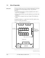
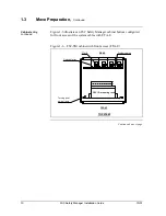
Figure 1-1
Typical Electronics Room Layout.............................................................................. 3
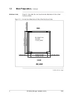
Figure 1-2
Location and dimensions of the cabinet bolt-down holes ......................................... 6
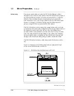
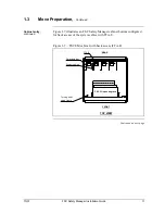
Figure 1-3
FSC-SM cabinet with back access (FTA-T).............................................................. 7
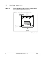
Figure 1-4
FSC-SM cabinet with front access (FTA-T) .............................................................. 8
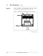
Figure 1-5
FSC-SM cabinet with front and back access (FTA-T) .............................................. 9
Figure 1-6
FSC-SM cabinet with front access (FTA-E) ............................................................ 10
Figure 1-7
FSC-SM cabinet with back access (FTA-E) ........................................................... 11
Figure 1-8
FSC-SM cabinet with front and back access (FTA-E) ............................................ 12
Figure 1-8
Placement of equipment onto lumber ..................................................................... 14
Figure 1-9
Placement using a mobile lifter ............................................................................... 16
Figure 1-10
Lifting equipment by mobile lifter of crane .............................................................. 17
Figure 1-11
Lifting equipment by mobile lifter of crane — part 2................................................ 18
Figure 1-12
Eyebolt crane method ............................................................................................. 19
Figure 2-1
FSC-SMM front plate .............................................................................................. 29
Figure 2-2
Redundant FSC-SM UCN cabling .......................................................................... 30
Figure 2-3
Typical routing layout of internal wiring between I/O modules and
FTA-T via SICs ....................................................................................................... 31
Figure 2-4
Typical routing layout of internal wiring between I/O modules and
FTA-E via SICs ....................................................................................................... 32
Figure 2-5
FSC Safety Manager cabinet power connections ................................................... 34
Figure 2-6
Connection of the UCN ........................................................................................... 40
Figure 4-1
US System Status display....................................................................................... 51
Figure 4-2
US Engineering Main Menu display ........................................................................ 52
Figure 4-3
US NIM Build Type Select Menu............................................................................. 53
Figure 4-4
US UCN Node Configuration display ...................................................................... 54
Figure 4-5
US Node-Specific Configuration display ................................................................. 55
Figure 4-6
US Process Point Building display .......................................................................... 56
Summary of Contents for FSC-SM
Page 2: ... ...
Page 6: ...iv FSC Safety Manager Installation Guide 10 01 ...
Page 12: ...x FSC Safety Manager Installation Guide 10 01 ...
Page 32: ...20 FSC Safety Manager Installation Guide 10 01 Left blank intentionally ...
Page 54: ...42 FSC Safety Manager Installation Guide 10 01 Left blank intentionally ...
Page 70: ...58 FSC Safety Manager Installation Guide 10 01 Left blank intentionally ...
Page 74: ... ...
Page 75: ... ...